Download
1 / 12
120 likes | 138 Views
This study presents initial findings on aerosol production within an IFE chamber environment, detailing models used and results from two test cases. The study identifies areas for improvement in the existing models and suggests enhancements for future research. The research covers the radiative gas dynamics, wall condensation, aerosol, and wall thermal response models, along with the setup of the IFE chamber. The results from the test cases provide valuable insights into aerosol properties and flow characteristics in the chamber. The study concludes with recommendations for advancing the models, including incorporating ion-induced nucleation and multi-component aerosol simulation capabilities.

E N D
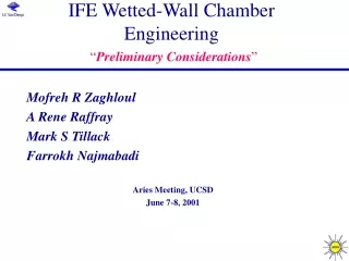
Preliminary Results on:Aerosol Production in the Post-shot IFE Chamber Environment J.P. Sharpe, INEEL Fusion Safety Program Discussion Topics: • Brief Description of Models • IFE Chamber Setup • Case 1 Initial Conditions and Results • Case 2 Initial Conditions and Results • What’s Next?
Description of Models 1-D Radiative Gas Dynamics Model • Eulerian model on fixed mesh • atomic physics package gives ionization, recombination, and radiation rates, but doesn’t work well for high Z (needs improvement) Wall Condensation Model • based on net molecular flux- needs refinement Aerosol Model • single component particles • includes homogeneous growth, condensation growth, coagulation, diffusion, and convection • no deposition or ion-induced nucleation Wall Thermal Response Model • not fully incorporated
IFE Chamber Setup • spherical chamber with a radius of 6.5 m • surrounded by liquid Pb wall • HIB fluxes used: 458 MJ yield Nodalization: 100 nodes of equal volume Properties of Pb used for Preliminary Analysis: Vapor Pressure Surface Tension and Density
Case 1: Heat Flux on Wall • all energy from shot deposits on wall and vaporizes material • no energy deposition in vapor, no plasma • initial chamber P is Psat at Twall = 874 K (0.075 eV) • evaporated mass injected at Tboil (0.34 eV) • some material expands into chamber, cools, and condenses This case serves as a reference for aerosol generation in an IFE chamber. Particle sizes and numbers are likely conservative for the IFE system, since energy deposited in vapor impedes particle formation, as does vapor pumping.
Case 2: Input from BUCKY* • initial chamber conditions given at 2 µs by BUCKY simulation of HIB target (remapped to match nodalization for the aerosol model) • does NOT include heating by debris ions • total chamber mass at 2 µs was 37 kg; mass convected from wall acts as source for aerosol • assumed constant Twall = 1160 K (0.1 eV) *Thanks to Don Haynes for providing BUCKY results…
Region 1 Region 2 Region 3 Region 4 Case 2 Results: Aerosol Properties
What’s Next… • complete wall thermal model to better predict Twall and condensation rate onto wall • add ion-induced nucleation to aerosol model • add an improved atomic physics package • add accounting of vapor energy deposition and vapor removal by a pumping system • extend model to multi-component aerosols to allow simulation of Flibe condensation