Download
1 / 29
290 likes | 325 Views
Explore gas phase synthesis methods, including homogeneous nucleation and other techniques, for generating quantum dots with high quantum yields and applications in nanocrystal LEDs and cells labeling. Discover advantages, disadvantages, and detailed insights into various gas phase growth reactors.

E N D
Gas Phase Growth Techniques for Quantum Dots Weiqiang Wang Department of Mechanical Engineering, University of Rochester Muzhou Jiang Department of Electrical and Computer Engineering, University of Rochester April 1st, 2007
Outline • Introduction; • Gas phase synthesis methods; • Homogeneous nucleation methods; • Other methods; • Prospective advances for gas phase techniques; • Summary;
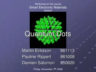
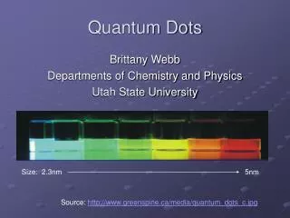
What is quantum dots? • size-dependent • discrete energy spectrum • quantum confinement • theoretically high quantum yield • single-electron transistor • coulomb blockade effect Quantum dots Diameter: 2-10 nm No. of atoms in diameter: 10 - 50 No. of atoms in quantum dot vol. : 102 - 105 various sized cadmium selenide (CdSe) quantum dots.
Great potential in applications Cells labelled with quantum dots Nanocrystal LEDs Brighten
Gas Phase Growth Technology— methods for preparing nanoparticles in the vapor phase Advantages • highest purity relative to liquid or solid state process • Cheap alternative to vacuum synthesis • Continuous process • Good performance in producing multicomponent materials • Good in process and product control Disadvantages — Aggregation
Gas phase synthesis methods Homogeneous nucleation methods • Aerosol reactors • Inert gas condensation • inert gas evaporation (IGE) • Laser vaporization • Expansion-cooling • Spark source • Furnace flow reactors • Plasma reactors • Laser reactors • Flame reactors Other methods • Laser ablation • Spray systems
Furnace flow reactors Heating particles with Oven sources on surfaces — limited operating temperature — impurities + simplest heating systems Shematic diagram of the Furnace flow reactors Schematic diagram of the aerosol generation, sizing and reaction process. Deppert et al. (1996) J. Crystal Growth. 169, 13-19
Plasma reactors Injecting thermal plasmaintothe sample particles; Decompose them fully into ions and atoms; React or condense afterwards; + high cooling rates — uniformity of the products Schematic diagram of a plasma reactor
Laser reactors Using laser energy to heat sample particles • highly localized heating and rapid cooling Shematic diagram of the Laser reactors TEM of the iron ultrafine particles Majima et al. (1994) Jpn. J. Appl. Phys. 33, 4759-4763.
Flame reactors Employing the flame heat to initiate chemical reactions • inexpensive method • simplest method for producing very high temperatures (< 3000K) • most commercially successful method Schematic of flame reactor. TEM’s of iron oxide/silica nanocomposites Zachariah et al. (1995) Nanostruct. Materials 5, 383-392.
Inert gas related techniques • Inert gas condensation • Inert gas evaporation (IGE) (Sputtering) • early (1960s), straightforward; • evaporation of a material in a cool inert gas (He or Ar); • low pressures conditions ~100 Pa; • suited for production of metal nanoparticles; • a reactive gas could be included; • different vaporization methods; -a method of vaporizing materials by bombardment with high velocity ions of an inert gas (Ar or Kr ); -in vacuum systems, below 0.1 Pa; -the composition of the sputtered material is the same as that of the target; -a very clean environment; but further processing difficult;
Inert gas condensation Al particles1 bismuth particles2 1. Granqvist, et al. (1976) J. Appl. Phys. 47, 2200–2219. 2. Wegner et al. (2002) Chem Eng Sci. 57, 1753-1762. Modeling Cross-section sketch of the inert gas condensation system The flow in the condenser using ammonium chloride particles2 Velocity vectors calculated for the configuration.2
Inert gas evaporation (IGE) (Sputtering) Alternative: electron beam. Schematic drawing of the deposition system. Synthesis for Al, Mo, Cu91Mn9, Al52Ti48 and ZrO2 Al2O3 and SiO2 nanoparticles. TEM: bright field dark field Urban et al. (2002) J Vac Sci Technol B 20:995-999.
Laser related techniques • Laser vaporization • uses a laser to evaporate a sample target; • vapor is cooled by collisions with the inert gas; • suits for many kinds of materials; • directional high-speed deposition of the particles; • the control of the evaporation from specific areas of the target; • the simultaneous or sequential evaporation of several different targets; • Laser ablation • a pulsed laser heats a very thin (<100 nm) layer of substrate material ; • resulting in the formation of atoms and ions also fragments of solid; • the pulse duration and energy determines the amounts of ablated particles; • target is usually rotated; • when used for producing films, this technique is called pulsed laser • deposition (PLD);
Laser vaporization SEM of weblike agglomeration of Si and Ge nanocrystals. The schematic diagram of the laser vaporization reactor. XRD spectrum of Ge nanocrystals. (a) Freshly made particles; (b) after 2 months of storage in air. Shoutian et al (1999) J. Cluster Sci. 10, 533-547
Marine et al. (2000) Appl Surf Sci. 154-155, 345-352. Laser ablation Schematic drawing of the laser ablation chamber. Si cluster size distribution for deposits prepared at different laser fluence.
Theoretical development Laser ablation Ablation crater morphology The operating conditions can be altered to select particle formation or film formation. Crater structures obtained with Nd:YAG laser at 266 nm, 4 mJ, 10 Hz. (A, B) copper and (C, D) silicon. Production rate as a function of He back-filled gas pressure changing laser pulse energy. Beam profile and irradiance in adjacent zones of the crater. Yamamoto et al. (1996) Nanostruct. Materials 7, 305–312. Davide et al. (2006) Spectro Acta Part B: Atomic Spectroscopy. 61, 421-432.
Expansion-cooling • Expansion of a condensable gas through a nozzle leads to cooling of the gas and a subsequent homogeneous nucleation and condensation. Modifications -multiple expansions; -expansion of a thermal plasma; -use a ceramic-lined subsonic nozzle; SEM pictures of zinc particles formed in nozzle. Bayazitoglu et al (1996) Nanostruct. Materials 7, 789–803.
Spark source A high-current spark between two solid electrodes be used to evaporate the electrode material for creating nanoparticles. A schematic diagram of the spark source A low resolution electron micrograph of Si clusters, and a high resolution electron micrograph of a section of one chain. Saunders, W. A. et al (1993) Appl. Phys. lett. 63, 1549–1551.
Spray systems • A simple way to produce nanoparticles is to evaporate micron-sized droplets of a dilute solution. • To use a nebulizer to directly inject very small droplets of precursor solution. (spray pyrolysis, aerosol decomposition synthesis) • Electrospray system. (small droplet from charged aerosol.)
Example of aerosol decomposition Schematic presentation of evolution of particle size, microstructure, and TEM images of approximately 100 nm TiO2 particles at reactor temperatures of (a) 800, (b) 1100, and (c) 1300۫C . Ahonen et al. (2001) J Aerosol Sci. 32, 615-630.
Example of electrospray system Schematic diagram of the eiectrospraying system Measured size distributions Chen et al (1995) Nanostruct. Materials 6, 309–312. Shapes of liquid meniscus
Recent developments and prospective advances for gas phase techniques • Advances in instrumentation; • Advances in modeling and simulation; • Advances in synthesis of multi-component nanoparticles;
Instrumentation -- Combination of laser-spectroscopic imaging techniques and laser ablation to image the plume of Si atoms and clusters;1 -- To combine localized thermophoretic sampling and in situ light scattering measurements to characterize particle size and morphology;2 -- Synthesis of nano-sized Al2O3 powders by a thermal MOCVD (Metal Organic Chemical Vapor Deposition) combined with plasma;3 -- TEM imaging for in-situ investigation;4 1Nakata et al. (2002) J Appl Phys. 91, 1640–1643. 2Cho J, Choi M. (2000) J Aerosol Sci. 31, 1077–1095. 3Kim H, et al. (2006) Key. Eng. Mater. 321-323, 1683-1686. 4Janzen et. al (2002) J Aerosol Sci. 33, 833–841.
Modeling and simulation A two-dimensional axisymmetric turbulent model of a particle generator with radial injection of a quenching gas. Aristizabal et al. (2006) Aerosol Sci. 37, 162–186
Modeling and simulation Simulation for a electrospary system CFD results of the reactor tube temperature and flow fields at wall temperatures of (a) 500 and (b) 1500˚C. Trajectories of three massless particles are shown by solid lines. Colour indicates temperature and black squares indicate 1s intervals Ahonen et al. (2001) J Aerosol Sci. 32, 615-630.
Synthesis of multi component nanoparticles Example of semiconductor quantum dots. Diagram of the growth process. AFM scans of AlGaInN particles. Solorzano et al. (2004) J. Cryst. Growth. 272, 186–191.
Summary A large number of synthesis methods of nanoparticles in the gas phase have been developed in the last 40 years. New approaches for improving control of particle size, morphology, and polydispersity are appearing regularly, the variety of materials that can be prepared as nanoparticles in the vapor phase is rapidly growing. Due to its high controllability, and the potential for high purity, large quantity production, gas phase synthesis of nanoparticles can be expected to be continue at a rapid pace, and to result in more examples of gas phase synthesized nanoparticles.
Click to edit company slogan . Thank You !