Download
1 / 31
320 likes | 534 Views
Adapted from B. Alberts. Molecular Biology of the Cell . 4th Ed. Garland Science: New York, 2002, pp. 638. CdS. Peptide. Quantum Dots for Neuronal Stimulation. Jessica Winter Dr. Christine Schmidt Dr. Brian Korgel. The University of Texas - Austin. Prosthetics. Retinal Implant.

E N D
Adapted from B. Alberts. Molecular Biology of the Cell. 4th Ed. Garland Science: New York, 2002, pp. 638. CdS Peptide Quantum Dots for Neuronal Stimulation Jessica Winter Dr. Christine Schmidt Dr. Brian Korgel The University of Texas - Austin
Prosthetics Retinal Implant. Boston Retinal Implant Project http://www.bostonretinalimplant.org/ Therapeutics Deep Brain Stimulator http://www.medtronic.com/ Microelectrode Arrays. P. Fromherz, et.al. PNAS, 98, p. 10457. Biosensors Electrical Stimulation of Cells
Ion Channel. Adapted from www.mhhe.com/biosciesp/2001_gbla/folder_structure/ce/m3/s1 nm Cell Diameter Cell Nucleus Ion Channel Retinal/Cochlear Implant Electrode 20 μm E-Beam Lithography Nanowire Quantum Dot Cell Receptors and Electronics Nerve Cell on FET Microelectrode Array. P Fromherz. Chem Phys Chem. 2002, 3, 276 Nanocrystals (Yellow) Bound to Nerve Cell Receptors. JO Winter, TY Liu, BA Korgel, CE Schmidt. Adv Mats 13, 1673, 2001.
Our Goal Exploit quatum dot – cell binding to create functional interfaces that directly interact with nerve cell receptors
5 nm Peptide HOOCH2CS SCH2COOH Core HOOCH2CS Peptide Shell Peptide SCH2COOH SCH2COOH Quantum Dots TEM of Nanoparticle. Lattice planes demonstrate crystallinity. CdS Passivated With Ligands. Ligand Passivationelectrically insulates the crystal and provides water solubility. Core-Shell Nanocrystal. The addition of a shell layer can further passivate the particle.
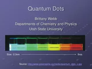
Quantum Dot Optical Properties • Size Tunable Fluorescence • Photostability • Narrow Bandwidth Quantum Dot Photobleaching (L) and Bandwidth (R) WCW Chan, S Nie. Science 281, 2016, 1998. Quantum Dot Fluorescent Emission Wavelengths M Bruchez, Jr., AP Alivisatos, et. al. Science 281, 2013, 1998.
HEAT Qdot-Cell Electrical Properties Dipole Moment Y Wang, N Herron. J Phys Chem 95:525, 1991. Light 380 nm Electron Tranfer Y Nosaka, et.al. Langmiur 11(4): 1170, 1995. e- + - Heat Transfer SR Sershen, et. al. JBMR 51: 293, 2000. Cell Quantum Dot
Aqueous Biologically Compatible Easily Passivated Undesirable Surface Defects Organic Few Surface Defects High Quantum Yield Requires Ligand Exchange for Biocompatibility Step 1: Chemicals Ligand Step 2: Chemicals Vacuum Injection Port N2 Quantum Dot Synthesis
Ligand:Cd Ratio pH Cd:S Ratio Size Ligand Length Size Nanocrystal Size Dependence JO Winter, N Gomez, S Gatzert, BA Korgel, CE Schmidt. Submitted, 2003
Cd:S Ratio pH Ligand:Cd Ratio Ligand Length- Different pH Ligand Length PL Quantum Yield PL Quantum Yield. Quantum Yield is maximum for intermediate sized particles ~ 2 nm. JO Winter, N Gomez, S Gatzert, BA Korgel, CE Schmidt. Submitted, 2003
Rapid Crystal Growth Reduced Passivation PL Quantum Yield Larger Smaller Particle Size Growth Mechanism Nanoparticle Quantum Yield As a Function of Particle Size. JO Winter, N Gomez, S Gatzert, BA Korgel, CE Schmidt. Submitted, 2003
pH 11 pH 5 pH 7 20 μm Non-Specific Binding Non-Specific Binding of CdS nanocrystals synthesize at different pH values. SK-N-SH Human Neuroblastoma Cells autofluoresce blue, nanocrystal fluorescence is yellow. SK-N-SH Neuroblastoma Cells. Minimum non-specific binding occurs with the same particles that display maximum quantum yield!
10 μm 10 μm Non-Specific Binding Non-Specific Binding of CdS (Yellow) to Primary Cells. Rat Neonatal Cortical Cells in Simultaneous Phase Contrast and Fluorescence Non-Specific Binding of CdS to Primary Cells. Rat Neonatal Cortical Cells in Phase Contrast
QUANTUM DOT 30 nm SECONDARY ANTIBODY ANTI-INTEGRIN ANTIBODY LIPID BILAYER Antibody Attachment to Cells. (To scale) Antibody Conjugation JO Winter, TY Liu, BA Korgel, CE Schmidt. Adv Mat 13(22): 1673, 2001
B A 60 m C Quantum Dot Neuron Interfaces formed with Antibodies. SK-N-SH Neuroblastoma Cells. 30 m 30 Antibody-Directed Binding Absorbance data from antibody-qdot complexes. Complexes (dashed) demonstrate both antibody (squares) and qdot peaks (solid). JO Winter, TY Liu, BA Korgel, CE Schmidt. Adv Mat 13(22): 1673, 2001
Cysteine - C QUANTUM DOT 3 nm C G G G G D R S RGDS PEPTIDE INTEGRIN RECEPTOR LIPID BILAYER Peptide Attachment to Cells. Peptide Conjugation GGG- Glycine-Glycine-Glycine Hydrogen R Group, Reduces Steric Hindrance RGDS- Arginine-Glycine-Aspartic Acid- Serine Binds Cell Surface Receptors: Integrins JO Winter, TY Liu, BA Korgel, CE Schmidt. Adv Mat 13(22): 1673, 2001
20 μm Peptide Directed Binding Absorbance and PL Emission of MAA (Black) and MAA-Peptide (Red) Conjugated Nanocrystals. FTIR Spectra of Free Peptide (Black) and Peptide Conjugated Nanocrystals (Red). Peptide Directed Nanocrystal Labeling. SK-N-SH Neuroblastoma Cells
Microelectrode Array SEM of De-Insulated Electrode (White). PMMA (gray) supports cell growth on Silicon (white) as seen in SEM. SK-N-SH Neuroblastoma Cells.
Oscilloscope Microscope Laser Micropositioner Preamplifier Computer Microelectrodes Cell Whole-cell Clamping System. Whole-cell Clamping
“Traditional” neuronal ion channels not expressed Resting membrane potential is abnormal Require large input of voltage to produce steps Die within a few minutes K+ Channels Open Computer Induced Voltage Steps Unlabeled (control) Voltage-Step of Cell Electrophysiology of Cultured Cells
15 μm 15 μm 15 μm 100 μm Phase contrast and fluorescence images of labeled cells. Phase contrast and fluorescence images of labeled cell. Cultured vs. Primary Neurons Cultured Neurons SK-N-SH Neuroblastoma Primary Neurons Rat Neonatal Cortical
Increasing Cell Viability • Labeling Procedure • Solvents (PBS, aCSF) • Washing and Adhesion • Coatings • Inorganic Caps (ZnS, silica) • Biological Agents (BSA, polylysine)
80 μm 80 μm Labeling Procedure Old Method New Method
Future Work • Examine biocompatible qdot coatings – BSA and PEG • Continue alternative binding approaches – con A • Organic Quantum Dots – CdTe • Alternative presentations of qdots – SAMs
Conclusions • Nanocrystal synthesis conditions alter spectroscopic properties • Antibodies and peptides may be conjugated to nanocrystals for targeted cell binding • Unprotected quantum dots may be toxic to cells, especially primary cell lines
Prosthetics Retinal Implant. Boston Retinal Implant Project http://www.bostonretinalimplant.org/ Therapeutics Deep Brain Stimulator http://www.medtronic.com/ Microelectrode Arrays. P. Fromherz, et.al. PNAS, 98, p. 10457. Biosensors Electrical Stimulation of Cells
Acknowledgements Personal Funding NSF IGERT Fellowship NSF Graduate Research Fellowship Collaborators Dr. Richard Morrisett Dr. Adam Hendricson Graduate Students Natalia Gomez Felice Shieh Project Funding Texas Higher Education Coordinating Board (ARP) NSF DARPA Undergraduates Tim Liu Sam Gatzert Sheila Chin Facilities Center for Nano and Molecular Materials (Welch Foundation) Texas Materials Institute Advisors Dr. Christine Schmidt Dr. Brian Korgel
Ion Channels Voltage Gated Ion Channel Activation. A depolarization of the membrane surfaces attracts charged segments of the ion channel protein, opening the pore. H Lodish, A Berk, SL Zipursky, P Matsudaira, D Baltimore, JE Darnell. Molecular Cell Biology. W. H. Freeman & Co., New York: 2000, Figure 21-13.
r Dipole Moment CdSe dipole moment ~ 32 Debye Alivisatos, et. al. J Phys Chem 97:730, 1992. http://hyperphysics.phy-astr.gsu.edu/hbase/electric/dipole.html Nanoparticle Dipole Interaction with Ion Channels. The dipole moment produced by particle optical excitation may be strong enough to elicit a membrane voltage potential change.
- - - - + - - - + + + + + - - - - + + + + + Debye Screening Debye Screening of the Dipole-Induced Electric Field. The electric field is screened by ions in solution, reducing the effective dipole moment.
10 mm x 10 mm Silicon Chip 2 X 1 mm 30 um 35 um 2 X 2 mm 5 x 5 um Electrode Bond Pad Bond Pad Insulated by PMMA Gold Bond Pad Microelectrode Array Design