Download
1 / 16
160 likes | 184 Views
This presentation summarizes the document sent to the SuperB collaboration and outlines future plans for electronics, trigger, and data acquisition. It includes relevant information for the overall experiment architecture.

E N D
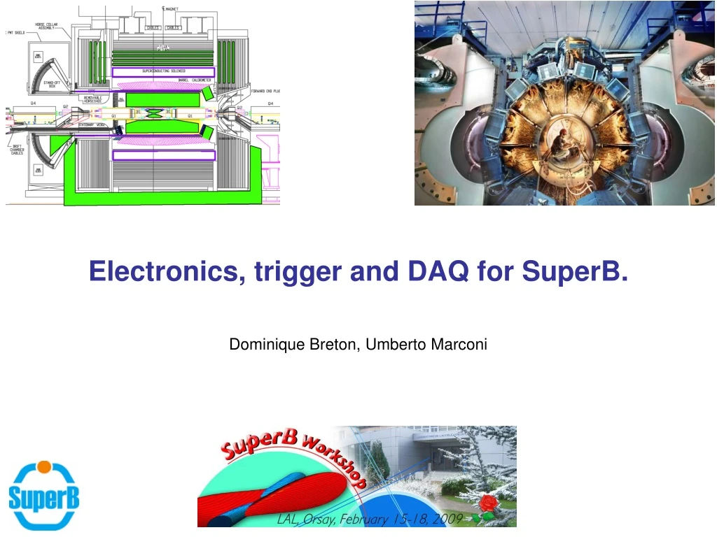
Electronics, trigger and DAQ for SuperB. Dominique Breton, Umberto Marconi D.Breton, U.Marconi, Orsay SuperB Workshop – February 15th 2009
Electronics, trigger and DAQ for SuperB. • Editors: D. Breton (LAL Orsay) and U. Marconi (INFN Bologna). • This presentation aims at summarizing the document sent to the collaboration three days ago and defining the plans for future activities towards the TDR. • It contains information we presented and collected during the last meetings dedicated to electronics, trigger and DAQ. Information recognized as relevant to constraint the overall architecture of the experiment is listed in the document and will be presented in the following slides. • In preparation of this document, editors had several meetings and got help from colleagues that they really wish to thank: • C. Beigbeder, M. Bellato, A. Cotta Ramusino, I. D'Antone, G. Dubois-Felsmann, D. Galli, I.Lax, S. Luitz, J. Maalmi, G. Maron, M. Morandin and M. Villa. • Definitions: in this document, in order not to make the understanding harder, acronyms used in BABAR have been used to name the different main elements of the system, as already done in former presentations. This does not preclude from eventually changing these names. • If you are interested in a summary of BABAR’s electronics architecture, have a look at the talk done by D. Breton in Roma at the computing workshop last December. D.Breton, U.Marconi, Orsay SuperB Workshop – February 15th 2009
Working conditions and introductory remarks (1) • RF in SuperB: ~ 450MHz • Bunch crossing (BX) rate in SuperB: RF/2 = 225 MHz. • If 450 MHz => evaluate the potential implications on the electronics system (however it shouldn’t affect the architecture described here) • 225 MHz: too high a frequency to be used directly to drive the electronics • => system clock running at RF/8 = BX/4 = 56.25 MHz: a good compromise • It permits operating the electronics effectively without synchronizations issues. • The clock can be multiplied locally to run sub-systems faster if needed. • Trigger rate is expected to be of the order of 100 kHz at 1036. • The sole Bhabha’s background: 50 kHz ? • baseline target rate of about 150 kHz. • However, some uncertainties remain on these numbers, as well as unavoidably on the final/real event size • data flow should be scaled with a rather wide margin. • Moreover, since we would not like a luminosity upgrade to force us to redesign the electronics, the trigger rate should not be a limitation by itself when moving the working conditions up to the maximum value foreseen for the instantaneous luminosity. D.Breton, U.Marconi, Orsay SuperB Workshop – February 15th 2009
Working conditions and introductory remarks (2) • L1 trigger primitives are produced by the Electromagnetic Calorimeter and by the Drift Chamber at a rate of a few MHz (7 MHz like in BABAR is a baseline). • SVT may give a hand. • High BX rate + rather slow detector signals used for triggering purposes • => impossible to precisely point to the event time T0 for event readout • => a readout window has to be foreseen • Window width is assumed to be roughly of the order of 1 s. • It may however be smaller and detector dependent, in order to reduce the bandwidth and optimize the dataflow. • But this reduction is eventually limited by the time precision of the trigger primitives • Operating at a L1 output rate of the order of 100150 kHz, with a readout time window of about 1 s => overlap probability of the time windows of about 10%. • It is possible to overcome problems related to the overlapping (data retransmission and bandwidth occupation) by means of having a FEE output stage suitably designed D.Breton, U.Marconi, Orsay SuperB Workshop – February 15th 2009
Working conditions and introductory remarks (3) • There is no reason to fix a minimum distance between consecutive triggers at the architecture level (down to very small numbers which may then become problematic at the FEE level). • Neither to specifically limit their number in a burst (this will come from dataflow). • => those constraints should only depend on the trigger system itself. • Due to the time precision of trigger primitives, a minimum distance of about 100ns between triggers is highly probable. • Data buffers have to be sized in order to avoid dead-time in the desirable proportion, and a throttling system has to be running accordingly. • We don’t see reasons in favor of addressing events for data readout in the L1 buffer RAM (asynchronous operating mode) with respect to working with a L1 constant latency (synchronous operating mode). • The synchronous mode indeed offers an easier understanding of the system, together with an eventual much easier commissioning. • It also permits having an autonomously running FEE. • Any loss of synchronization will immediately be detected. D.Breton, U.Marconi, Orsay SuperB Workshop – February 15th 2009
Clock and fast control system (1) • There are two options to master the clock phase in a wide system: • Ensure it by design; • Measure it and compensate for offsets. • First solution is easier to implement (in terms of electronics complexity) and should thus be studied first. • Yet, the second one has to be kept on tracks. • Main requirement for the clock jitter => data transmission rate on the high speed links used throughout the detector (expected to be of the order of 1015 ps rms) • Physics requirements (50100 ps rms: not yet precisely known). • TOF PID option => much better resolution (~ 5 ps rms). • About these fast links => talk in parallel session Monday at 4:30PM • Possible solution: distributing the clock according to the physics requirements then cleaning it locally, to drive the serializers with good enough precision/stability. • => need of a very precise quartz (like the QPLL system on LHC) • For TOF option, as the TO of the events is related to the 225 MHz BX, a specific design has to be studied. • Future generation FPGA should include jitter cleaners, but they still may not safely operate in a radiation environment, so their behaviour under radiation exposure needs to be preliminarily validated. D.Breton, U.Marconi, Orsay SuperB Workshop – February 15th 2009
Clock and fast control system (2) • Concerning clock distribution, it would be wise avoiding the GBT as the baseline solution for the optical links of SuperB. • We do not master the GBT time schedule, which is linked to the SuperLHC upgrade project • We may not be able to ensure any precise time schedule for a dedicated production. • We therefore recommend developing another solution than GBT for the transmitters located on the FEE side, based on commercial components. • Commercial components, as said before, require being validated for radiation (rad-tolerant level => not LHC-like !). • Off the shelf FPGA’s can be safely employed on the barracks side instead (GBT-like !) • Solution based on commercial components should be easily adequate for all sub-detectors but SVT (especially layer 0) • SVT is the most critical element concerning radiation mitigation. • However, it might be wise avoiding specific developments for its control and readout system. • One may imagine a solution where a common standard readout interface would be located close, but out of the high radiation zone, and connected to the detector FEE with low cost differential copper lines. D.Breton, U.Marconi, Orsay SuperB Workshop – February 15th 2009
Clock and fast control system (3) • As quoted above, clock jitter requirement will principally be linked to data rate in the fast serialized links. Said data rate should thus be adjusted in order to optimize requirements on both jitter and dataflow. • About the distribution of the readout signal in case of L1 accept, we foresee two options: • Sending the LSB’s of the trigger tag to the front-end to put it in the event header (BABAR like) • Sending a simple pulse (LHCb like for instance) and then use a counter running in the FEE to tag the trigger. • this solution requires a global command being sent to synchronize all the counters in the FEE system. • A synchronous calibration signal also has to be distributed to the FEE. • Partitioning has to be studied. • Concerning the communication protocol, we noticed that 104-bit commands were sent between FCTS and ROMs. • could this size be reduced ? • If kept, the 104 bits message transfer delay should however still remain compatible with a “100ns” inter-trigger minimum distance, when sent over new type of multi-gigabit link (needs four 56MHz clock periods) . D.Breton, U.Marconi, Orsay SuperB Workshop – February 15th 2009
L1 Trigger • In order to try to reduce the L1 trigger latency, the clock used in the FPGA’s can be synchronously multiplied thanks to internal PLL’s (up to 225 MHz for instance). • While synchronous at 56 MHz, the peak output rate of the central trigger processor has to be linked to its time precision capacity. • It is highly probable that this rate should not exceed 7 MHz, thus giving a mean minimum distance between triggers of 142 ns. • However, a distance of 71ns may also be possible if the central trigger is able to refine the event T0 like in BABAR, or if trigger primitives are produced at a higher rate (14 MHz). • Seen the foreseen rate of Bhabha’s, it would be useful to implement a Bhabha veto at the level of the L1 trigger. • This could be considered only as a future upgrade of the system, but the model chosen then has to take it into account from the start. • This would be even more desirable in the case of a luminosity upgrade • => avoiding putting too high a pressure on the bandwidth required for dataflow which may overcome the original requirements, even with safety margins. D.Breton, U.Marconi, Orsay SuperB Workshop – February 15th 2009
Dataflow • The system has to be totally triggered, which means data will be stored in buffers waiting for L1 trigger, then sent to DAQ upon it. • This implies that trigger primitives must have their own dedicated path towards trigger processors. • The system has to be able to handle the constraints on trigger distance and rate, as well as to optimize the dataflow across the links. • overlapping events will be treated in such a way as to simplify the FEE and provide full and clean events to HLT and DAQ. • For this purpose, useful event data will only be sent once between FEE and ROM, and truncated event data will be restored in the ROM before events be further processed. D.Breton, U.Marconi, Orsay SuperB Workshop – February 15th 2009
Front-end model • The model chosen for trigger distribution and event selection in the FEE has to fulfill as simply as possible all the following requirements: • being synchronous • being safe and monitorable (any loss of synchronization with trigger and FCTS has to be detected immediately) • trigger latency and readout window width should be fixed but programmable in the FEE like in BABAR • in case of overlapping, data should be sent only once between FEE and ROM together with overlap information, and full event data should be restored in the ROM before being sent to HLT and DAQ. • If ever the window width would have to be variable on a per event basis, this should only be driven by physics and not by any other system driven consideration, because this makes the model much trickier. • In case a Bhabha veto were implemented in the L1 trigger, even as an upgrade, it may become necessary to be able to get back in time to read the corresponding data in case a physics events would sit on the tail of the Bhabha. • The front-end model has to take this requirement into account. • => see the model simulations in the talk in parallel session Monday at 4:00PM D.Breton, U.Marconi, Orsay SuperB Workshop – February 15th 2009
Radiation mitigation • Due to the potential radiation level on the detector, only really useful electronics has to sit in there. • the FEE design has to get rid of any unnecessary complexity. • Moreover, the DAQ and control systems have to be informed if any problem due to single events occurred on the front-end. • Components used there have to be validated for radiation (especially concerning their robustness to Single Event Latch-up which may be destructive). • Safe configuration of FPGA also has to be guaranteed • Either by using rad-tolerant families • Or by scanning the configuration and correcting errors (may cause deadtime) • In the FEE, critical flip-flops have to be triple-voted, and memories have to use redundancy codes. • It is very important to take radiation into account at the very beginning of the TDR phase, because if having a mitigated system without radiation is fine, the opposite could be a catastrophe! D.Breton, U.Marconi, Orsay SuperB Workshop – February 15th 2009
HLT Trigger and pre-processing boards (1) • The HLT trigger input rate is expected to be of the order of 150 kHz, with an event size which we will try to keep below 100 kB/evt. The input bandwith of the HLT is therefore impressive, at the level of LHC experiments. • HLT could be then effectively implemented as a versatile software trigger system, by means of an online computing farm of commodity PCs, performing the event building and running the selection algorithms. • Events passing the HLT will be transmitted to the storage system by the farm nodes. • In order to inject data into the farm, data has to be formatted according to a given industrial standard. A modular interface layer of pre-processing boards placed between the FEE and the online farm, actually sitting in place of the ROM in BABAR, is then required. • In addition to already quoted post-overlap restoration, these pre-processing boards may be used to perform in pipeline mode complex operations (noise filtering, feature extraction, data compression, etc.) and to finally perform format conversion of data to the industrial standard. D.Breton, U.Marconi, Orsay SuperB Workshop – February 15th 2009
HLT Trigger and pre-processing boards (2) • Event fragments aggregation in multi-event packets can be foreseen at the level of the processing boards in order to optimize data transmission to the farm (bandwidth occupancy optimization vs packet size and packet transmission rate). • Destination addresses of the packets to the farm nodes can be introduced at the pre-processing boards level via FCTS, allowing for dynamical load balancing of the farm computing resources, the latter requiring the farm nodes data when idle in pull mode. • Pre-processing modules should be designed to serve the entire collaboration, defining the standard for data transmission from the FEE to the HLT. • In case the farm nodes were not asking for more events to process and in order to avoid a potential overflowing of the buffers of the pre-processing boards, the possibility of throttling the L1 trigger is also foreseen. D.Breton, U.Marconi, Orsay SuperB Workshop – February 15th 2009
Conclusion • This presentation and the document it refers to describe the base of the architecture we want to set up for SuperB, and will be the template used for the TDR. • It still has to get enriched and refined so please interact with us! • A few remarks: • We need a more precise estimation of the data rates and number of links for all the sub-detectors, in order to be able to scale the system, and to optimize its topology. • Our first approach is based on L1 buffers located in the FEE, but options where the latter would be located farther in the dataflow chain can be studied (data driven models). • As a first reach, we recommend setting up as soon as possible a team in charge of validating commercial components for the implementation of high speed optical links, in order to provide a solid proposal for the TDR. • We still would like to get neutron fluence maps. • We invite you to attend the parallel electronics session tomorrow to get more details about most of the points raised here today. D.Breton, U.Marconi, Orsay SuperB Workshop – February 15th 2009
Parallel electronics session Monday at 4:00PM 16:00->18:00Parallel V - detector electronics (Convener: Dominique Breton, Umberto Marconi ) Description: D.Breton, U.Marconi, Orsay SuperB Workshop – February 15th 2009