DAQ and Trigger for HPS run
150 likes | 301 Views
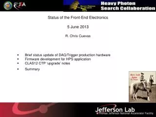
DAQ and Trigger for HPS run. Sergey Boyarinov JLAB July 11, 2013. 1. Requirements and available test results 2. DAQ status 3. Trigger system status and upgrades 4. Timeline. Requirements. 50kHz event rate, 100MB/s data rate (calorimeter 25MB/s, muon 6MB/s, SVT 33MB/s)

DAQ and Trigger for HPS run
E N D
Presentation Transcript
DAQ and Trigger for HPS run Sergey Boyarinov JLAB July 11, 2013 1. Requirements and available test results 2. DAQ status 3. Trigger system status and upgrades 4. Timeline
Requirements • 50kHz event rate, 100MB/s data rate (calorimeter 25MB/s, muon 6MB/s, SVT 33MB/s) • Those requirements about twice less then JLAB DAQ parameters • Dead time < 1% • During test run event rate was limited by several kHz because of beam conditions. Performance test was conducted by lowering thresholds, event rate 120kHz was achieved with FADC readout only with small data rate (no SVT)
all modules are available FADC250 Flash ADC Crate Trigger Processor Sub-System Processor Signal Distribution Trigger Interface
Pipeline TDC System (VME64X/VME) NOTE: will not use it if FADCs produce timing and scalers (timing is not implemented yet)
DAQ System Overview Calorimeter and Muon System Readout: 442 channels of 12bit 250MHz Flash ADCs for Calorimeter, up to 256 additional FADC channels if Muon system is used SVT readout system (ATCA) Optional: 85ps resolution pipeline TDCs with discriminators Maximum 7 crates (3 VXS, 3 VME64X, 1 ATCA) JLAB CODA DAQ software Staff Scientist in Hall B, two supporting groups (DAQ group and Fast Electronics group, 5 people each) Status: ready, currently in use by several test setups
FADC: pulse integration, report charge and time CTP: search for clusters using 3x3 crystals window SSP: two calorimeter clusters; cuts on cluster multiplicity, geometry (with respect to beam) and energy (two thresholds) Status: ready, used in 2012 HPS test run, some improvements are needed 3-stage trigger processing – FADC/CTP/SSP
Framing the Trigger Data from the FADC250 HPS Test Run 5 bit value extracted from Channel energy sums 3 timing bits used to encode 4ns clock for TOT sample time 16 Bytes every 32ns (5ADC + 3 timing bits) 1 Byte per channel HPS trigger process runs @4ns ‘Integrate’ over 4 frames Report every 128ns FADC250 retains functions for VME data readout of signals when system trigger is received For HPS a 13 bit value will be extracted for the channel energy sums. 3 bits will be used for timing encoding to restore 4ns clock. Requires 32bytes in 32ns so serial transfer speed must double to 5Gbps per lane. 6
CTP Cluster Finder CTP Algorithm: Add energy from hits together for every 3x3 square of channels in ECAL Hits are added together if they occur (leading edge) within a programmable number of clock cycles (4ns ticks) If 3x3 energy sum >= cluster energy threshold report cluster to SSP (time, energy, position and 3x3 hit pattern ) Not in Test Run, but will be added in Production Run • Notes: • Reported cluster information has 4ns timing resolution based on when cluster condition is satisfied • Reported cluster position is not centroid – it is within +/-1 crystal index of centroid
MoreTrigger Monitoring Histograms Stage 1 (FADC) • Scalers per channel (readout threshold based) Stage 2 (CTP) • Individual ADC channel pulse energy histograms Stage 3 (SSP) • Cluster Hits (Position) • Cluster Hits (Position+Energy) - Depending on resources in SSP • Trigger cut accept/reject:
Diagnostic Additions Summary • In addition to trigger system diagnostics: • Online event analysis will be used to be compared against trigger event data for immediate verification (for each trigger cut, cluster energies, & positions) – at least a fraction of events • With identical ADC readout/trigger pulse processing and high trigger energy resolution, very precise agreement can be expected between trigger & readout
Conclusion • DAQ in 2012 test run was nearly final configuration, do not expect any problems in final HPS DAQ system • Trigger logic changes will be relatively small – we expect this to be an easy implementation because we will have new revisions of hardware (“CTP2” / “SSP2”) which have more resources than before • Trigger parameters should be much easier to follow with with the additional of energy calibration for trigger right at the FADC • Remaining effort will be invested in diagnostics for real-time feedback and additional offline analysis support • 2 JLAB electronic engineers (Ben Raydo, Scott Kaneta) assigned to the firmware development, 160K in budget will cover remaining work