Download

1 / 10
100 likes | 267 Views
Shorter PSB Main Dipoles Magnet Design. Newborough 21 st June 2012. Shorter PSB main Dipoles. Outline. Review of requested length reductions - 0.25 m reduction - Injection magnet design (BHZ162) Magnetic circuit design Coil design - Operation Trim supplies (missing NI)

E N D
Shorter PSB Main DipolesMagnet Design Newborough 21st June 2012
Shorter PSB main Dipoles Outline • Review of requested length reductions • - • 0.25 m reduction - Injection magnet design (BHZ162) • Magnetic circuit design • Coil design • - • Operation • Trim supplies (missing NI) • Further length reduction (time constant reduction) • - • Summary • - • Questions Shorter PSB Main Dipoles – Magnet Design
Shorter PSB main Dipoles Possible length reductions • 0.15 m – Installation of vacuum valves(Difficult to justify, another solution exists) • 0.5 m - Maximum requested(Too high field!) • 0.25 m - Half maximum requested, if magnets centres could be off-set (Preferred solution) • 0.44 m to allow for external dump (fits with magnet centre off-set, 0.25 m reduction) • 0.32 m comfortable limit? (Advantages of being even shorter?) Shorter PSB Main Dipoles – Magnet Design
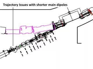
Shorter PSB main Dipoles 0.25 m reduction - Injection magnet design (BHZ162) BHZ 11 BHZ 162 NewDipoles Shorter PSB Main Dipoles – Magnet Design
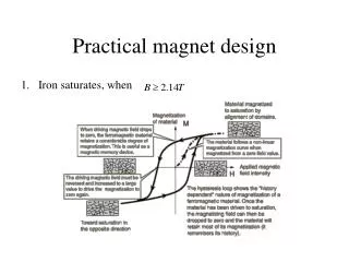
Shorter PSB main Dipoles 0.25 m reduction - Injection magnet design (BHZ162) Saturation reduction on ring magnets planned for 2 GeV operation Shorter PSB Main Dipoles – Magnet Design
Shorter PSB main Dipoles Magnetic circuit design + 150 mm side plate Iron length 1287 mm (-250 mm) Height - 1.715mm (+ 200 mm) Width - 775 mm (+ 75 mm) ~25 mm offset towards circulating beam. Shorter PSB Main Dipoles – Magnet Design
Shorter PSB main Dipoles Coil design Now - 12 turns (2 x 6) Short - 14 turns (2 x7) As today the BHZ 162 will require a special coil design with hollow and solid conductor combined, ~10 mm more space is available. Shorter PSB Main Dipoles – Magnet Design
Shorter PSB main Dipoles Operation • The required number of turns for a reduction of 250 mm is 14.3 • The missing current (~2%) can be supplied by trim supplies (2 per magnet – inner and outer gaps) • The trim supplies will allow the integrated field to be matched to the other ring magnets • It will be desirable that the time constant of the shorter dipole is smaller than the existing magnets (trims can slow the field but not speed it up!) • Characterization / field tracking maybe possible with a spare BHZ magnet before installation avoiding the need for a dedicated online measurement Shorter PSB Main Dipoles – Magnet Design
Shorter PSB main Dipoles Operation Advantages of being even shorter? • If the currently magnetic end plates of 25 mm in thickness are changed to a non magnetic stainless steel, it will be possible to reduce the eddy current effects and thus minimise the time constant of the magnet. • The mechanical reduction will remain at 250 mm, however the magnetic length will be reduced. • This additional reduction in magnetic length increases the required trim current from 2 to 6%, due to a greater mismatch in the required number of turns (14.3 to 14.8). This increase may allow more flexibility to match the integrated field in the existing magnets, but power supply costs will increase. • The increase in field due to the further reduction in magnetic length still remains within comfortable limits. Shorter PSB Main Dipoles – Magnet Design
Shorter PSB main Dipoles Summary • Shorter main bending magnets seem feasible. Two designs will be required with different coil arrangements between the BHZ162 and BHZ11 due to the injection chamber passing through the yoke. • Higher field levels will dictate an increase of ~200 mm in height, ~75 mm return yoke (interior), ~150 mm return yoke (exterior side plate) to minimisesaturation. • Trim supplies to compensate for missing turns will be required, depending on the design of the magnet they must deliver between 2 and 6 % of the required current. The trim supplies will match the integrated fields in the shorter magnets to the existing ring magnets. Two supplies per magnet will be required, one for the inner rings and one for the outer rings. • The characterization of the shorter magnets and field tracking with the old magnets can be made before installation. An online measurement may be necessary for operation – further study is needed. • The two shorter magnets will increase the total load (resistance/inductance) of the PSB main circuit by up to 5 %. • The cost for the magnets is estimated at 1 MCHF for 2 units plus 2 spares (the cost of cabling, power supplies, controls etc… is not included), design and fabrication is at least 2 years. Shorter PSB Main Dipoles – Magnet Design