Download
1 / 26
260 likes | 389 Views
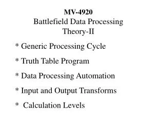
This document comprehensively explores advanced data processing automation, focusing on the Generic Processing Cycle and Truth Table programming. It outlines the critical steps of data handling, including reading detector inputs, processing through logic, and writing actuator commands. By leveraging input/output transformations, it simplifies complex computations, enabling efficient mapping of human operations to machine processes. Additional examples illustrate the hardware implementation of Truth Table programs, showcasing real-time problem-solving and optimization strategies in complex systems.

E N D
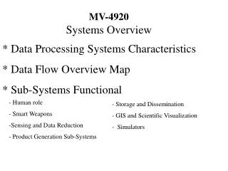
MV-4920 Battlefield Data Processing Theory-II * Generic Processing Cycle * Truth Table Program * Data Processing Automation * Input and Output Transforms * Calculation Levels
Generic Processing Cycle Program Detector Status to Actuator Commands output input WRITE READ Actuator Detector
Generic Processing Steps 1) Read - Reads Detector Content into Input array for the calcualtion phase 2) Process - Execute the program which connects a set of Inputs to a set of Outputs 3) Write - Sends Actuator Commands from calcualtion output array into Actuator 4) Wait - reset go back to step 1 Generic Data Structures Detector Readings - Detector name, detector content Actuator Commands- Actuator Name, Actuator content Input - Memory Cell Name, Memory Cell Content Output - Memory Cell Name, Memory Cell Content
READ The Transform from detector name space to program input name space is done by the Read function enable Detector Readings READ Input disable Read ( radix* DetectorNames, radix* Input){ Enable (DetectorNames+I); For (I=0,I<Number of detector names,I++){ *(Input+I) = *(DetectorNames + I); } Disable (DetectorNames+I); return; } Low level simple assignment example
WRITE The Transform from program output to actuator commands is done by the WRITE function enable Actuator Commands WRITE Output disable Write( radix* ActuatorNames, radix* Output){ Enable (ActuatorNames+I); For (I=0,I<Number of ActuatorNames,I++){ *Output = *(ActuatorNames + I); } Disable (ActuatorNames+I); return; } Low level simple assignment example
Generic Truth Table Program Radix InputTable [MaxInput Possibilities] Radix OutputTable [MaxOutputPossibilities] TruthTableProgram(Radix Input,Radix Output) { while(This<MaxInput Possibilities){ if (Input = = InputTable[this]) {Output = OutputTable[This]; return;} This = This + 1; } return; } Input Output
Truth Table Program INPUT OUTPUT Detector names Actuator names 1 2 3 …. Dmax 1 2 3 …. Amax 0 1 1 0 1 0 0 1 0 1 0 1 1 0 0 0 1 1 1 0 1 1 1 1 ... 0 0 0 0 1 0 0 0 0 1 0 0 1 1 0 0 0 0 1 0 1 0 1 0 ... If this do that All possible actuator commands All possible detector content states
Some Properties of the Truth Table Program Any calculation doable with a Turing machine can be written as a Truth Table Program. The program execution steps are trivial. All the complexity is in the Input and Output tables. The Input and Output Tables can get very big. For example suppose besides the immediate detector input the program also considers the past history ie. The memory of the machine. Then the Input would contain the not just the detector readings but also the the content of all the memory cells. HOW BIG? Assume there are Dmax detectors reporting one of “Dc” readings and Mmax memory cells reporting a “0 or 1” each of then the total number of Configurations is DcDmax * 2Mmax Each additional cell will multiply the volume of possibilities by the number of different contents that can be read from the cell. If this number of input possibilities requires a response to Amax actuators with “l” levels the total truth table array is Amax * l * DcDmax * 2Mmax
Simple Surface Seeker Example Input: 2 detector 2 levels L R 0 1 L R L N R Output: 1 actuator 3 positions wheel L N R Program: Truth Table Detector Name L R 0 0 0 1 1 0 1 1 Reason no target seek left target right go right target left go left target center go straight Actuator name Wheel L R L N
0 0 0 0 0 0 1 1 1 0 1 0 1 1 1 1 EXAMPLE: HARDWARE IMPLEMENTATION OF A TRUTH TABLE PROGRAM L R N R L EXAMPLE: LOOKUP Table Implementation OUTPUT = TRUTHTABLE[INPUT];
How many gates does it take to Implement? For a system with INmax 2 state inputs and outputs the Total Gates = 2* (INmax +1)* 2INmax Suppose each set of these gates are a micro meter in size.How big a problem could you fit into a sphere of size R in meters. Total Gates = 4/3 *1024*R3
How fast could a calculation be done ? Time to for the speed of light to go from the center to the surface and back. T = 2R/c T = (2R/c )= 2/c (3 /4*10-24*G)1/3 = (2/c)* 10-6* (3 2 /4)1/3 ((IN+1)2IN )1/3 = ~ 5* 10-14 ((IN+1)2IN )1/3 IN= 30 bits T= 3.4x10⁻¹⁰ R = 10 cm IN = 100 bits T = .004 sec R = 1.2 x10⁶
TRICKS TO REDUCE IMPLEMENTATION COST Truth Table Program solves any problem in real time but complex problems cost a lot what can you do? * Reduce bits * use value changes * some patterns cannot happen * collect patterns with the same solution * Add time ( program steps) * calculate each possibility when it happens * Hybrid - pre-calculate partial solutions
Data Processing Automation * WHAT IS AUTOMATION? The transfer of what a human does to a machine. * Automation Steps 1) Learn the human operation sequences. 2)Build a machine that automatically executes machine operations 3) Map the human to sequences of machine operations 4) if mapping not complete add machine operations and go to 2. * We already have a machine that does any calculation we can imagine. * So what is left to do? Learn how the human writes the truth table program.
How is the program written? Input and output possibilities are defined by all possible content configurations in the space of input and output cell names. The programmer visualizes the meaning of an input content configuration possibility. The programmer decides for each possible input what is the appropriate output and writes this decision into a truth table. The programmer goes to the next possible content configuration until all possible input configurations are exhausted.
Context and Reason for Program Supplied by Programmer Programmers World Concept Program Detector Status to Actuator Commands input output READ WRITE
Programmer Writers Process Programmers World Concept Output Meaning Input meaning decision Interpret detector readings in terms of input Interpret Meaning of output in terms of Actuator commands Program input output
output DETECTOR LEVEL Program Transforming The Program to a Higher Level Programmers World Concept input output HIGHER LEVEL Program Transform Transform input READ WRITE
Steps to Solve the Intercept Problem at a Higher Level Example Specific General functions Select Hunter and Target Object Space. Solution Minimized distance. 1) Find a space in which the Problem Solution decision can be made 2) Make the decisions in this space 3) Transform from measurements to Decision Space and add detectors as necessary. 4) Transform from Decision to Command Space and add Actuators as necessary. Write the Program (Input Hunter and Target Object Space ,Output Hunter and Target Object Space ) Write the Transform (Readings Detector Space , Input Hunter and Target Object Space ) Write the Program (Output Hunter and Target Object Space ,Commands Actuator Space )
Step 1) Find the Decision Space Solution is to close the distance Hunter Position Xh,Yh,Zh,Th Target Position Xt,Yt,Zt,Tt
Step 2) Write the Interceptor Truth Table Program(3x3x3 Example) Output cell names memory to actuators Input cell names measured memory 0 1 2 0 1 2 0 1 2 0 1 2 … 2 0 0 0 1 1 1 2 2 2 0 0 0 … 2 0 0 0 0 0 0 0 0 0 1 1 1… 2 X 0 1 2 0 1 2 0 1 2 0 1 2 … 2 Y 0 0 0 1 1 1 2 2 2 0 0 0 … 2 Z 0 0 0 0 0 0 0 0 0 1 1 1… 2 0 1 2 0 1 2 0 1 2 0 1 2 … 2 0 0 0 1 1 1 2 2 2 0 0 0 … 2 0 0 0 0 0 0 0 0 0 1 1 1… 2 0 1 2 0 1 2 0 1 2 0 1 2 … 2 0 0 0 1 1 1 2 2 2 0 0 0 … 2 0 0 0 0 0 0 0 0 0 1 1 1… 2 0 0 0 ... 0 T 0 0 0 H 0 0 … 0 B 0 0 0 0 T 0 ... 0 T T 0 0 H T 0 … 0 B T 0 0 0 H 0 ... 0 T H 0 0 H H 0 … 0 B H 0 0 0 0 0 ... 0 0 0 0 T 0 0 H 0 .. 0 T 0 H 0 0 0 000 0 H 0 0 … 0 B 0 0 0 0 0 0 ... 0 T 0 0 0 H 0 0 … 0 B 0 0 0 0 T 0 ... 0 T T 0 0 H T 0 … 0 B T 0 0 0 H 0 ... 0 T H 0 0 H H 0 … 0 B H 0 0 … 0 0 0 ... 0 0 0 0 T 0 0 H 0 .. 0 0 0 0 0 T 0 00H 0 0 0 0 … 0 0 0 0 0 Name dimensions All Possibilities
H1 T1 H2 T2 H1 T1 H2 T2 H3 Hout T3 How is the Intercept program written? Visualize Next Possible Input Configuration Predict new position based on constant velocity: Xh3 = 2*Xh2 - Xh1, Yh3 = 2*Yh2 - Yh1, Zh3 = 2*Zh2 - Zh1 Xt3 = 2*Xt2 - Xt1, Yt3 = 2*Yt2 - Yt1, Zt3 = 2*Zt2 - Zt1 Calculate Hunter’s best velocity Change: R = (Xh3-Xt3)2 + (Yh3-Yt3)2 + (Zh3-Zt3)2 X = (Xh3-Xt3) /R Y= (Yh3-Yt3) /R Z= (Zh3-Zt3) /R Calculate desired position Xhout = Xh3 + X , Yhout = Yh3 + Y , Zhout = Zh3 + Z Calculate the best Move Write Output decision Next =Next+1
Step 3 ) Detector Reading to Object Space Transform Transform( Detector readings| HunterPosition,TargetPosition) Transform program in Truth Table format Corresponding Hunter Position, Target Position Xt,Yt,Zt,Xh,Yh,Zh Instant HunterPosition,TargetPosition All possible Detector readings D,Az,El,f,Xh,Yh,Zh Instant Detector readings
How is the Detector Reading to Object Space Transform Programmed? 2) Find Detector Reading Context o f D 5)Single Instant Transform Xt=O*cos(el)*cos(az) Yt=O*cos(el)*sin(az) Zt=O*sin(el) O = m*f 1) paramterize Object Space F Az El 4) Add Additional Detectors for Target Positioning GPS receiver Xh Yh Zh Th 3) add Additional Detectors for Hunter positioning
How is Object Space to Actuator Command Transform Programmed? Spectrum of Actuator Command 1) If the vales Yr,Pr,Th were applied 2) The change in position in Vehicle coordinates in T F = Th * drag F = Th * drag U= F * (1-cos(Pr)/2) R= F * (1-cos(Yr)/2) 3) Transform from Vehicle to Object Space Coordinates X Vehicle F Y = to U Z space R 4) The change X, Y, Z Would result in the position. PitchRate YawRate Thrust Reverse calculation to get Actuator Commands U R F Desired X, Y, Z from Program
THEORY II SUMMARY Programmers World Concept input output OBJECT LEVEL Program Transform Transform input output DETECTOR LEVEL Program READ WRITE T a k e s P r o c e s s i n g H i g h e r L e v e l s Automation Trend D a t a F l o w to LEVELS OF ABSTRACTION Time