Download

1 / 22
220 likes | 303 Views
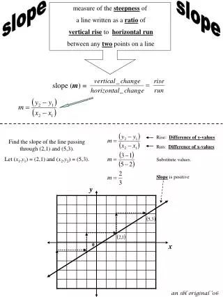
Hardware Pace Using Slope Detection. Tony Calabria 10/22/2012. The Concept. Subhead text here. ECG + Pacemaker Signal. Slope Detection. Frequency components of ECG lie in 0.05 – 150Hz. Frequency of PACE components reside in >1KHz.

E N D
Hardware Pace Using Slope Detection Tony Calabria 10/22/2012
The Concept • Subhead text here
Slope Detection • Frequency components of ECG lie in 0.05 – 150Hz. Frequency of PACE components reside in >1KHz. • Monitor for Slope of Pace Signal while ignoring ECG signal slope. • Need to measure the rate of change of voltage to determine slope: Differentiator Circuit • Output signal should not respond to ECG • Pace Signal should only pass • Looking for a specific dV/dT • Pace Spec required to meet: • 2mV Amplitude Signal • 100us Period Signal
Alert/Trigger • Need to trigger an Alert bit when Pace is present • Using a window comparator, a pulse can be created once the output of the Differentiator Circuit shows a change outside the preset window. • Threshold limits set externally depending on amplitude of Differentiator Output at minimum Pace signal spec requirements (2mV, 100us). • SR Latch can be used to latch and hold the value of the Comparator output indicating a Pace Signal has occurred. • Mandatory that an ECG Signal does not create a response by the comparator outputs.
Differentiator Circuit • Looking for specific slope: dV/dT change • Duration of slope produces output amplitude • R used to set gain • Frequencies above fc, the circuit is acting as ordinary inverting amplifier Source: http://circuitalley.phpnet.us/circuit3.html
Window Comparator • The Differentiator output signal will idle within the window when PACE is not present • When PACE appears, the output of the differentiator circuit will toggle, forcing the voltage outside the limits of the window comparator • The output to pulse low. • That low pulse must be latched and held until read back by a uC or GPIO
SR Latch • SR Latch output high once Window Comparator outputs low pulse • Reset line is pulled high • Latch stays until reset by user. • Would need to reset with every QRS waveform if wanting to monitor for pace with each heartbeat
Circuit Stability Subhead text here
Differentiator Circuit Analysis C2 used for Op amp Stability and High Freq gain control
Differentiator Circuit Stability Rate of Closure = 20dB/Dec
Time Domain Analysis 2mV Amplitude 100us Period Model to replace internal ADS1298 Pace Amplifier
Time Domain Analysis Cont. Set threshold point for Window Comparator Pace input pulse
Window Comparator Threshold ~ 2.77V ~ 2.48V
Testing Subhead text here
Pace Card Design • Designed to mate with ADS1298ECG-FE board • Top side populated for PACE OUT 2 and bottom side for PACE OUT 1 • Requires one 5V supply • SR Latch Outputs routed to ADS1298 GPIOs • Analysis required for circuit stability
Unstable Design Differentiator out Comparator out SR Latch
Stable Design Differentiator out Comparator out SR Latch