Download
1 / 41
410 likes | 525 Views
Final Presentation – Part B. Picture Manipulation using Hardware. 10.06.2013. Dual-semester project. Presents by- Uri Tsipin & Ran Mizrahi Supervisor– Moshe Porian. Agenda. Intro – Problem, Project’s goals, Algorithm Previous System – Explained

E N D
Final Presentation – Part B Picture Manipulation using Hardware 10.06.2013 Dual-semester project • Presents by- Uri Tsipin & Ran Mizrahi • Supervisor– Moshe Porian
Agenda • Intro – Problem, Project’s goals, Algorithm • Previous System – Explained • New Top Architecture – Additions and modifications • µArchitucture- components description, simulations and testing • GUI • Testing • Problems during the project • Conclusions
Intro • Many military and civilian application use image manipulation as an integral part of their function Helmet mounted displays Medical procedures Army surveillance gear
Problem Image Processing algorithms such as: • Image Rotation • Zoom • Crop Image which implemented by software are: • Slow • Heavy power consumers • Large space consumers Solution • Hardware implementation of the algorithms using Board with FPGA and External Memory
Project’s Goals Implement the following algorithms using FPGA: • Full panoramic rotation: 0 to 360 degrees • Support of Zoom function • Support of Crop-Image function • Minimum image distortion
(x_start,y_start) Input image
Top Architecture – Previous System UART TX Path RX Path UART WBS WBM WBM Host (Matlab) Wishbone INTERCON WBS Memory Management WBS WBM VGA Display WBS Display Controller WBM IS42S16400 SDRAM WBS SDRAM Controller VESA
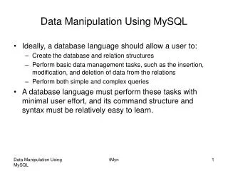
Top Architecture – New UART TX Path RX Path UART WBS WBM WBM Host (Matlab) Wishbone INTERCON WBS Memory Management WBS WBM VGA Display WBS Display Controller WBS Image Manipulation WBM IS42S16400 SDRAM WBS WBM SDRAM Controller VESA
Data Flow - Ilustration UART TX Path RX Path UART WBS WBM WBM Host (Matlab) Wishbone INTERCON WBS Memory Management WBS WBM VGA Display WBS Display Controller WBS Image Manipulation WBM IS42S16400 SDRAM WBS WBM SDRAM Controller VESA
Image Manipulation – New Block • Parameter registers- holds user parameters (angle,zoom,crop) • Address Calculator – Calculates "matrix address" of 4 pixels that are required for the bilinear-interpolation and converts the "matrix address" into a 1D SDRAM address • Bilinear Interpolator – Calculates a mean average between 4 pixels • Image Manipulation Manger – Controller for the block • Internal RAM- 1 KB • WBM/WBS- top block interfaces Image Manipulation WBS Param Registers Addr Calculator WBM Biliniar TYPE Reg ImgMan Manger ReadProc WriteProc WBM RAM
WBS Param Registers Parameter Registers WBM Addr Calculator Biliniar TYPEReg ImgMan Manger WBM ReadProc WriteProc RAM • New registers were added to the system in order to hold the user parameters, which are required for image manipulation. • Registers addresses were expanded to 5bit addresses (up-to 32 registers)
WBS Param Registers Address Calculator WBM Addr Calculator Biliniar TYPEReg ImgMan Manger WBM ReadProc WriteProc RAM • Main Goal – Calculates "matrix address“ of 4 pixels that are required for the bilinear-interpolation. • Method - Given a current pixel index in the output image, the unit will calculate the origin addresses of the pixel, by the following formula: • Inputs: • User parameters (zoom factor, sin/cos[angle], crop indexes) • Row/Col index (current calculating coordinate) • Outputs: • TL,TR,BL,BR coordinate address • Delta Row, Delta Col- holds the weight for billinear interpolation. • Out of range • Valid,Finish
WBS Param Registers Addr. Calc. -Improved µArchitucture WBM Addr Calculator Biliniar TYPEReg ImgMan Manger WBM ReadProc WriteProc RAM
WBS Param Registers Bilinear Interpolator WBM Addr Calculator Biliniar TYPEReg ImgMan Manger WBM ReadProc WriteProc RAM • Main Goal – Calculates the mean average of 4 given gray-scale values. • Formula – • Inputs • 4 pixels, 8bit grey scale • Weight fraction (row/col) • Outputs • Result pixel (the mean average of the input) • Valid signal
WBS Param Registers BilinearInterpolator –µArchitucture WBM Addr Calculator Biliniar TYPEReg ImgMan Manger WBM ReadProc WriteProc RAM
WBS Param Registers Image ManipulationManager –(1) WBM Addr Calculator Biliniar TYPEReg ImgMan Manger WBM ReadProc WriteProc RAM • Main Goal – Control the data flow within the image manipulation block and send Read/Write requests to other units using the wishbone protocol • Method – the controller is implemented via a several FSM’s. • Enable output for display
WBS Param Registers Image ManipulationManager – Main Features WBM Addr Calculator Biliniar TYPEReg ImgMan Manger WBM ReadProc WriteProc RAM • RAM- internal RAM which stores results before write-back to SDRAM. Burst RAM size is generic- 1024 bytes. • Top FSM- controls the data flow between inner units and the main system. • Read FSM- controls the read process, sub-phase to the top FSM. • Write FSM- controls the write process, sub-phase to the top FSM. Writes the RAM contents to SDRAM.
WBS Param Registers Image ManipulationManager – Interfaces WBM Addr Calculator Biliniar TYPEReg ImgMan Manger WBM ReadProc WriteProc RAM • WBM_rd- interface for read purposes. • WBM_wr- interface for write purposes. • WBS- interface for writing to parameter registers.
WBS Param Registers Image ManipulationManager - µArchitucture WBM Addr Calculator Biliniar TYPEReg ImgMan Manger WBM ReadProc WriteProc RAM ImgMan Manger Coordinate Process TOP FSM Address Calculator Process Read FSM Write FSM Bilinear Process Generic RAM (1024 Bytes)
WBS Param Registers Img. Man. Manager - FSM WBM Addr Calculator Biliniar TYPEReg ImgMan Manger WBM ReadProc WriteProc RAM
Test Benches • Purpose- test functionality of the IMG_MAN new block, debug problems during integration • Implementation- Matlab, text files from ModelSim
Test Bench (1)- ADDR_CLAC • ModelSim generates txt file with the calculated addresses Output.txt Addr_calc_tb Addr_calc Output 1,1 Output 1,2 600 1 Output 1,3 . . . . 1 2 3 800 Output 512,512
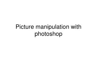
Test Bench (1)- ADDR_CLAC cont. • Using Matlab, the output image is created Zoom=x4 Angle =60 deg X Start =30 Y Start =29
Test Bench (2)- IMG_MAN • ModelSim generates txt file before/after writing back the pixels values to internal RAM, in order to make sure the new block is correct Image Manipulation WBS Param Registers Addr Calculator WBM Biliniar TYPE Reg ImgMan Manger WBM ReadProc WriteProc RAM
Synthesis, P&R System Timing Results Latency- time from end of transmission to end of manipulation- 435422720 ns, or 0.4354 sec. At 100 MHz: 43542272 cycles
GUI Set Parameters Load image Click to transmit Make sure Transmission enabled Select image Debug option – synthetic image Expected Output Transmission time
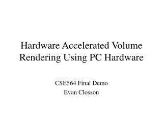
Lab Testing Display GUI DE2 PC
Debugging in Lab Uart Serial out Mem Type Reg DBG MSB REG Sine Reg
Main milestones • Learn previous system • Degenerate system to project goals • Build new block, functional TB, interfaces to main system (Wishbone protocol) • Integrate the new block with main system • Lab testing and debugging
Test results Demo Video
Working methods • Top down design • Pipeline • Test bench • Results comparison with Matlab(Golden Model) • Components documenting • Working on lower resolution during simulations • design with generics parameters (change resolution) • Synchronize files via SVN.
Problems during the process (1) • Working with fractures First version of addr_calc used fixed point package. Problem occurred during synthesis. Solution- work with regular std_logic_Vector, with relevant adjustments.
Problems during the process (2) • Trigonometric calculations (sine, cosine) planed to be executed by VHD process, consumes expensive hardware resources. Solution- calculate Cos/Sin by software (Matlab).
Problems during the process (3) • Timing issues- synthesis timing results did not meet the requirements. solution- break arithmetic calculations into parts (piping).
Problems during the process (4) • Resolution issues- high resolution simulations takes more than 3 hours. solution- working with lower resolution and diagnose the errors before high resolution simulations.
Problems during the process (5) • Resolution issues- failed passing simulations while upgrade to high resolution. Even though generics were used, it was hard to detect the specific errors. solution- update VHDL generics (on the main system-Pixel manager), update counters.
Conclusions/lessons (1) • Pipeline makes the throughput shorter. With “heavy” calculations, it is recommended to break the arithmetic process.
Conclusions/lessons (2) • Working with generics parameters make the design more flexible.
Conclusions/lessons (3) • Top down design divides the coding procedure into stages, allows more than one person to work on solution, allows parallel work.
Time Table – 2012-2013 3 months delay