Download
1 / 22
220 likes | 351 Views
Iron Loss Calculation in a Claw-pole Structure. Avo Reinap David Martinez Muñoz Mats Alaküla. Objective. Core loss calculation in a claw-pole structure Estimation of magnetic loading MEC vs. FEM Estimation of magnetic losses according to B locus

E N D
Iron Loss Calculation in a Claw-pole Structure Avo Reinap David Martinez Muñoz Mats Alaküla Industrial Electrical Engineering and Automation Lund University, Sweden
Objective • Core loss calculation in a claw-pole structure • Estimation of magnetic loading MEC vs. FEM • Estimation of magnetic losses according to B locus • Core loss model verification • Core loss measurement of a single-phase claw-pole motor • Optimal size for the claw-pole structure Iron loss calculation in a claw-pole structure
Construction of the motor • Magnetring • plastic bounded ferrite (PA12); • lateral polar magnetization; • Claw-pole halves • soft magnetic composite (Somaloy500+LB1); • A progressive radius of the claw-poles causes difference between the rest positions and a starting torque; Iron loss calculation in a claw-pole structure
Core loss formulation • Loss separation • The formulation is the same for an alternating and rotating field • Hysteresis loss • Rate of change of energy used to affect magnetic domain wall motion • Eddy-current loss (classical eddy currents) • Due to induced currents flowing in closed paths within magnetic material • Anomalous loss • Eddy current loss due to magnetic domain wall motion Iron loss calculation in a claw-pole structure
Core loss calculation • On the basis of the variation and location of magnetic loading the specific core loss can be predicted • Magnetic loading evaluation is based on • Magnetic Equivalent Circuit (MEC) • 3D Finite Element (FE) modeling; • A posteriori core loss prediction approach • The hysteresis loss calculation and the loss coefficients differ between the alternating and rotating field Iron loss calculation in a claw-pole structure
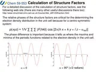
Core loss energy per cycle • The specific core loss energy per remagnetization revolution at constant speedω • Loss coefficients are derived from the measurements that consider sinusoidal magnetization • In general, the flux density locus forms an ellipse that is a combination of alternation and circular rotation Iron loss calculation in a claw-pole structure
Magnetic Equivalent Circuit • A model of 1D elements describes the main flux paths in the 3D core at the alignment position; • The node potential method is used to calculate the scalar magnetic potential, branch fluxes and magnetic loading for each element; Iron loss calculation in a claw-pole structure
Magnetic Equivalent Circuit • When the rotor is located at any other position different from the alignment position, there will be flux flow through the symmetric surfaces; • The extended formulation that considers the connection between the node points on the periodicity surfaces Iron loss calculation in a claw-pole structure
Finite Element Analysis • The FE method allows to discretize the machine in a larger number of 3D elements; • The solution of the magnetostatic problem is calculated at a number of positions in the excitation cycle; • A commercial package, Opera-3D, is used for FE field calculations; Iron loss calculation in a claw-pole structure
3D FE Core Loss Calculation • Core loss calculation is carried out according to the magnetic loading in the centre of each hexahedral element; • The trajectory of the field locus over excitation cycle is calculated for each element; • The predicted specific loss is attached to the core geometry; Iron loss calculation in a claw-pole structure
Magnetic loading • The magnitude of flux density components BθBrBz • At the alignment position the radial Br and the axial Bz components are dominating • The rotation gives rise to the circumferential Bθ component Iron loss calculation in a claw-pole structure
The trajectory of field locus • The ratio of the minor axis of ellipse to the major axis determines the contribution of the alternating and rotating components to the total core losses; • The flux alternation (a line) occurs mainly in the base core • The flux density loci are close to a circle in the claw-poles • The flux variation forms ellipse in the flanks Iron loss calculation in a claw-pole structure
Specific hysteresis loss energy The static loss energy is the work required to overcome magnetic friction and to magnetize the core during the magnetization period, which in turn is equivalent to the area of the major hysteresis loop • Alternation (B vector forms a line) • Dissipated energy due to magnetization cycle equals to the area of hysteresis loop • Rotation (B vector forms a circle) • Specific rotational hysteresis loss per cycle can be expressed in terms of four elements; Iron loss calculation in a claw-pole structure
Hysteresis loss • A rotational field causes nearly twice the loss, compared to the loss produced by an alternating field with the same peak value at a midrange flux density; • At saturation the loss caused by a rotation field decreases to the levels well below that caused by an alternating field; • No local minima (minor hysteresis loops) • No biased field variation (asymmetric hysteresis loop) Iron loss calculation in a claw-pole structure
Dynamic core loss • The dynamic loss energy per magnetization cycle depends on the frequency of the cycle • The loss energy is calculated according to the average of the position rate of change It is advantageous to use a single formulation combining all the dynamic losses, since then the loss coefficients can be calculated more easily from the measurements Iron loss calculation in a claw-pole structure
Static loss measurement • A calibrated dc motor is used to estimate: • the mechanic loss energy (Wfrict) to turn the shaft of the mechanic system; • the total loss energy (Wfrict +Whyst) to turn the shaft when the claw-pole core is included; • The static characteristics differ 60% between • the shaft magnetic torque seen from the dc motor • the cogging measured from the mechanic equilibrium Iron loss calculation in a claw-pole structure
Dynamic loss measurement • The higher rotation speed gives rise to • Windageloss (Pdyn,mech) of the mechanic system (no claw-pole core included); • Dynamic core loss (Pdyn,core) of the claw-pole stator that includes air dynamic losses in the air-gap and friction between the shaft and core; Iron loss calculation in a claw-pole structure
Optimization • Optimization routine looks for the optimal combination of the size and pole numbers for the claw pole motor, while the stator volume is constant; • The inner radius of the inner stator is varied from 0 to 20mm; • The length to width ratio of the cross-section of the claw-pole structure is changed from ¼ to 4; • The number of poles is changed from 4 to 44; Iron loss calculation in a claw-pole structure
Peak torque • Peak torque and flux linkage of a claw-pole structure as a function of inner radius and pole number Flux density 0:0.1:1.5 T Iron loss calculation in a claw-pole structure
Hysteresis Loss • Hysteresis loss due to field loci of a claw-pole structure as a function of inner radius and pole number The specific hysteresis loss 0:200:2000 J/m3 Iron loss calculation in a claw-pole structure
Optimal core size • Soft magnetic composite (SMC) core has advantage of • Formingcomplex isotropic 3D core; • Lower dynamic core losses at higher frequencies; • The torque of the outer rotor motor that depends on the number of poles is limited by the leakage between the adjacent poles Iron loss calculation in a claw-pole structure
Summary • The simple MEC is sufficient to select the size of the core and to predict magnetic loading • Unless proper material data are used, the calculation method does not give reliable results • Hysteresis loss measurements show 35% higher loss than it was expected from the calculations • The dynamic core lossis underestimated as much as 60% at 100Hz; Iron loss calculation in a claw-pole structure