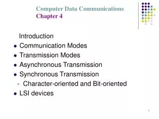
Transmission Modes
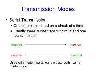
Transmission Modes. Different ways of characterizing the transmission. Timing of the transmission of the data bits. 0 1 0 1 1. Serial Data bits transmitted at different times One bit after the other Parallel Multiple bits transmitted simultaneously ( same time )

Transmission Modes
E N D
Presentation Transcript
Transmission Modes Different ways of characterizing the transmission
Timing of the transmission of the data bits 0 1 0 1 1 • Serial • Data bits transmitted at different times • One bit after the other • Parallel • Multiple bits transmitted simultaneously (same time) • Typically with different data “lines” for each bit 1 1 0 1 0 0 1 0 1 1 0 1 0 1 1
Simplex - one way (tv,radio, weather satellite) Device 1 Device 2 time data
Half Duplex - alternate each way (telephone, cb, ham radio) Device 1 Device 2 time data
Full Duplex - both ways same time (computer serial) Device 1 Device 2 time data
Timing between transmitter and receiver ASYNCHRONOUS • All transmissions are synchronized somehow • once per bit (Manchester) • once per byte • once per frame ….. • Asynchronous (means without synchronization) but DOES synchronize once per BYTE. • Awful name
1 0 1 1 0 0 1 1 0 0 0 StartBit Idle Idle Parity Data Stop Bit FIRST LAST Serial (asynchronous) Encoding
1 0 1 1 0 0 1 1 0 0 0 StartBit Idle Idle Parity Data Stop Bit Idle -> No information on the line Start Bit -> Defines the beginning of the byte Data -> Information (number of bits varies) Parity -> A check digit for correct reception (more later) Even/Odd/None Stop Bit-> A check for correct detection of start bit 1/1.5/2 bits long
Start Bit Timing Bit Centers Clock -> 4 times faster that bit rate 2 ticks from beginning is bit center 4 ticks from there is next bit center
More Timing Details - Figure 3.5 • Timer must be faster than the data rate • Degree to which faster dictates how close to center you can get • 16x (Fig 3.5.c.iii) shows only off 1/16th • 4x (Fig 3.5.c.ii) shows only off 1/4th • 1x (Fig 3.5.c.i) shows problems • Page is misleading • 1200/2400/9600 note is not for the diagram • i -> fastest data rate, iii -> slowest data rate • fastest clock ratio -> slowest data rate
Maintaining SynchronizationFigure 3.9 • DPLL digital phase locked loop • count for transition • if transition not seen as expected • adjust the timing interval by • adding 1 tick • subtracting 1 tick • on the next cycle. • Used in many coding techniques. • Book uses NRZI.. Forced change on 0, require a zero peridically.
Parity • Counts number of ones in DATA • Sets the parity bit to 1/0 • Even or • Odd • May not choose to use at all (None) • Not a good means of error detection • Error in one bit 10-6 … Error in 2 bits 10-1 • Assumes independence of bit errors … not always true
Parity examples PARITY (even) DATA 0 0 1 0 0 1 0 0 1 1 1 0 0 0 1 1 0 1 0 + 2 = 2 1 + 5 = 6 Use Second example and assume errors 1 0 1 0 0 0 1 1 1 0 0 0 0 0 1 1 1 + 4 = 5ERROR 1 + 3 = 4 ??????? 1 1 One can’t detect multiple bit errors properly!
Serial TransmissionMany concepts in one byte • Synchronization on a byte level • Framing with start and stop bit • Error detection with parity • What does this cost us?
Efficiency • A means of evaluating the nature of the cost to implements solutions to these fundmantal communication problems • (data)/(data + overhead) • Overhead is anything not part of that intended to be communicated for the receiver • Be careful to pick a time which is repetitive when evaluating. Choose the right time is everything.
1 0 1 1 0 0 1 1 0 0 0 StartBit Idle Idle Parity Data Stop Bit Efficiency Data 8 8 Efficiency = = = = .7272 Data + Overhead 1+1+ 8 + 1 11 1200 bps line modem = 1200 * .7272 = 872 bps ignoring idle!
Where would you see it? • On a PC it is the COM1, COM2 .. Port • Typically RS232 interface • 9 pin • 25 pin • or others • Modem, mouse, keyboard • ASYNCHRONOUS because one can’t tell when the data will be transmitted from one byte to the next
Review Modem Communication Serial transmission
Figure 2.31 • Interface between computer (dte) and modem (dce) • Not all lines used • Higher level controls present • request to send • clear to send • asynchronous across xmit/recv • interface can also be used for synchronous • line 16 • one interface … both async and sync
Figure 2.32Typical scenario • Notice the timing between dce / dte • Notice the timing between dce / dce • Scenario describes half-duplex • Full duplex minimizes the impact of “turnaround time” • revc • (turnaround) • send
Serial Summary • Same name (asynchronous) used for two concepts • lack of timing • Serial (byte transmission) • NOTHING in the name imples BYTE transmission but that is how it is used • Synchronizes once per byte • assumes clocks will remain synchronized until the end of the byte • Illustrates OVERHEAD
So what is Synchronous? • Synchronizes • once per block of data not per byte • Typically faster rates • USB ports on a PC (find rates on www) • see www.pcs.cnu.edu/~dgame/cs335/topics/usb.ppt • easier to understand after protocols • More complex framing (each of these are bytes typically) (end) errordetect DATA control sync sync
Sync byte/string • A pattern with which receiver can established synchronization • The longer it is (to a point) the greater the reliability of the synchronization • Like a start bit • (e.g. ) 0 1 1 1 1 1 1 0 • No idle times between bytes(bits) in the frame.
Figure 3.12 • SYN for character frames • 01111111 (idle) 01111110 (start and end) • synchronization maintained for frame duration
Character/bit stuffing • What if timing/framing flags in beginning or ending? • AND they are part of the data itself! • Stuff extra symbols if in data • Stuff even if “stuffed” version is in the data
Character stuffing Data STX SYN SYN ETX Expected End of Data STX SYN ETX SYN ETX ETX in data STX DLE DLE DLE SYN ETX SYN DLE ETX ETX in data DLE in data Receiver discards!
Bit Stuffing Basically the same! 5 zeros in a row, insert extra 0
Isochronous(periodic) • Asynchronous • irregular gaps between bytes • Synchronous • no gaps between bytes • gaps between blocks • Isochronous • REGULAR gaps between blocks • telephone PCM • 4000Hz -> 8000 samples/sec -> 8 bits/sample-> 64000 bps • What if on 1.5 Mpbs line?
AsynchronousSynchronousIsochronous Different arrival rates of bytes