Rerouting for Handoff in a Wireless ATM Network
330 likes | 477 Views
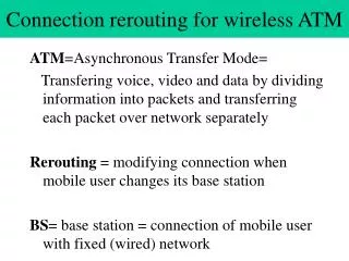
Rerouting for Handoff in a Wireless ATM Network. Akyol and Cox IEEE Personal Communication Magazine Oct. 1996. New era in telecommunications: Wireless communications + ATM Wireless ATM (WATM) Portable ATM Terminal + fixed ATM LAN/WAN WATM Needs: Higher Bandwidth & Mobility Handoff

Rerouting for Handoff in a Wireless ATM Network
E N D
Presentation Transcript
1 Rerouting for Handoff in a Wireless ATM Network Akyol and Cox IEEE Personal Communication Magazine Oct. 1996
2 • New era in telecommunications: • Wireless communications + ATM Wireless ATM (WATM) Portable ATM Terminal + fixed ATM LAN/WAN • WATM Needs: • Higher Bandwidth & Mobility • Handoff • The procedure by which a user’s radio link is transferred from one radio port to another through the network without an interruption of user connection. • In this article: • Summarize the handoff procedure in WATM • Propose: Nearest Common Node Rerouting (NCNR) • Comparison of NCNR with 5 other rerouting algorithms
3 Handoff Procedure • WATM consists of • radio ports (RP) • user terminals (UT) • network interface equipment (NIE) • Zone: • A group of radio ports that is connected to the same WATM interface equipment • Managed by the zone managementprocess (zone manager)
4 • Two levels in a handoff event: • Radio-level handoff • actual transfer of the radio link between two radio ports. • Network-level handoff • supports the radio-level handoff between one or more network interface equipment by rerouting and buffering. • Two kinds of handoffs • Intrazone Handoff (not discussed in this paper) • rerouting only at the same WATM NIEwithin the same zone • Interzone Handoff (discussed in this paper) • rerouting at one or more WATM NIEsacross different zones
5 • Assume • The zone manager • maintains a local lookup table of the network addresses of the neighboring zones • updates the table periodically by means of an update protocol between neighboring NIEs • The handoff transaction (not discussed in this paper) may be implemented using • either the current ATM signaling protocols (UNI 3.1) • or a migratory wireless ATM signaling protocol • These zones are interconnected by WATM switches.
6 Rerouting for Interzone Handoff • NCNR(Nearest Common Node Rerouting) • To perform the rerouting at the nearest ATM switching node that is common to both zones involved in the handoff transaction • Goal: • By eliminating unnecessary connections: • Minimize the resources • Conserve bandwidth
7 • Services that the WATM users subscribe: • Time-sensitive traffic types • e.g. audio, video. • may not tolerate delay • may tolerate cell loss • Throughput-dependent traffic types • e.g. data, file transfers, WWW access. • may tolerate delay • may not tolerate cell loss • Two different NCNR strategies: • for Time-Sensitive Traffic (NCNR-TS) • for Throughput-Dependent Traffic (NCNR-TD)
8 • Assume • The transmission delay and latencyof the links from the NCN to the zonesinvolved in the handoff are negligiblecompared to the the radio transmission medium.
9 NCNR for Time-Sensitive Traffic A B 1. A handoff session between zones A and B. Zone A - the present zone; Zone B - the candidate zone. 2. The zone manager of A checks to see if a direct physical link between A and B exists (Case 2A) If A is a parent of B... (Case 2B) If B is a parent of A... if no direct physical link between A and B exists go to Step 3.
10 2A. If A is a parent of B: Note: Parent - flat network: end point of user connection as root - hierarchical network:
11 2B. If B is a parent of A Note: Parent - flat network: end point of user connection as root - hierarchical network:
12 anchor • a network point that the user connection (end point) is forwarded through to candidate zone until the handoff is completed 2A. If A is a parent of B: • A notifies B • Established a new connection • A acts as an anchor • Once the handoff is stable, the connection stays.
13 2B. If B is a parent of A • A notifies B • Established a new connection • B acts as an anchor • Once the handoff is stable, B deletes the connection
14 B B 3. If A and B are not directly connected • A sends a handoff start messageto the end point (containing the ATM addresses of A, B, and the endpoint)
15 B B 4. • Upon receiving the handoff start message, the ATM switches along the path (from A to the end point) check to see whether all three ATM addresses are routed on different egress ports of the switch. • When the node is found, it is designated as the NCN. • The NCN sets the NCN bit in the handoff start message. • The rest of the switches on the path do not perform the egress port test.
16 B B 5. • The NCN forwards a reroute message to all of the switches located between B and itself. • The switch first checks for resource availability; • if available, then setup theconnections;if not available, then handoff fails and the involved parties arenotified.
17 B B 6. • When the reroute message is received by B, B sends a reroute acknowledge message to A. • The radio-level handoff is started. • The NCR starts to forward the user information to both A and B in a point-to-multipoint manner until the radio-level handoff is stable.
18 6 (cont.) • In a fading environment,a small motion of the mobile terminal may cause the radio link to switch back and forth between the two radio ports; hence, a point-to-multipoint link from NCN to both A and B ensures the timely delivery of time-sensitive information. • In the uplink direction, the information may be transmitted through either zone and correctly routed to the endpoint by the NCN. • The user information may be discarded at the zone which is not in contact with the user terminal.(if a zone has not received an uplink transmission from the portable in a given radio transmission frame.) • Occasionally, the portable may receive duplicate information. The duplicate information may be determined by the time sequence information and discarded accordingly.
19 B B 7. • If the radio-level handoff is successful (stable), the connection between A and the NCN is cleared by Aby sending a clear connection message to the NCN. • Any bufferedtime-sensitive data that has not expired will be transmitted to the current zone; • Expired data are discarded.
20 NCNR for Throughput-Dependent Traffic • Differs from the NCNR-TS: 1. In the downlink direction:- As the radio-level handoff (RLH) is started, user information is buffered at both A and B. - No downlink transmission until the RLH is completed. - Once the RLH is completed, the information is transmitted in a FIFO manner.
21 NCNR for Throughput-Dependent Traffic 2. - If A’s buffer is non-empty before the RLH is started, A’s buffer is transmitted to the user terminal if possible; otherwise, these data istransmitted to B and go in front of all other cells buffered in B. This preserves the cell sequence. 3. - In the uplink direction: - The traffic is transmitted through A if possible; otherwise, it is buffered at the terminal. - As the RLH is started, the user terminal starts tobuffer the user information. - Once the RLH is completed, the buffered information is transmitted.
22 NCNR for Throughput-Dependent Traffic • Multiple connections may be routed using the virtual path connection. • Assigning a virtual path identifier for connections between a user and multiple endpoints • Performing the rerouting on a virtual path instead of on a virtual circuit basis.
23 1. Yuan-Biswas Rerouting Scheme • Rerouting of connections at designated Handoff switching equipment (HOS). • It does not specify how the HOS is determined.Use the initial WATM switch as the HOS. • Assume the base stations are interconnected by permanent virtual circuits. • Handoff ports on the same WATM switch: • updating translation table in one switch • Handoff ports on the different WATM switches: • new connection is established before handoff is completed • forwarding cells to the user’s new WATM switch • Cell sequence is preserved • since the first switch acts as a handoff server (switch)
24 2. BAHAMA Rerouting Scheme • For wireless LAN • For flat network • The initial radio port acts as an anchor • After the handoff is completed, the initial radio port migrates the user connection to an optimal route provided that the portable stays in the coverage area of the new radio port for an extended period of time. • Cell sequence is preserved • since the cells are always routed by the anchor during the handoff • Use virtual path indicator in the ATM cell header for routing: simple (only the VPI needs to be changed)
25 Comparison of NCNR with Yuan’s and BAHAMA • Sameness: • all use cell forwarding ease of cell sequencing • all use the previous switch as an anchor cell sequencing • all do buffering either at anchor switch or the new switch • differences: • In NCNR, the buffering is only performed for throughput-dependent traffic and only when the radio-level handoff is being performed. • Yuan’s and BAHAMA do not allow connection between two radio ports while the handoff stabilizes. This causes delay problem for time-sensitive traffic.
26 Comparison of NCNR with Yuan’s and BAHAMA • Differences (cont.): • Yuan’s and BAHAMA fit in flat networks only.NCNR fits in either flat networks or hierarchical networks. NCN: minimize the Bandwidth, buffering is performed at the edge of network • For fast moving user in small coverage areas, rerouting usually occurs at the same NCN in NCNR minimize the bandwidth minimize the number of rerouting • BAHMA uses virtual path indicator. This is suitable for LAN but not scale well for WAN.
27 3. VCT: Virtual-Connection-Tree-Based Rerouting Algorithm • Virtual-Connection-Tree: • A root node is attached to the backbone ATM network.A number of radio ports (leaves) are connected to the root. • When a mobile terminal established an WATM connection, a VCT is formed. The mobile utilizes only one of the leaf nodes at a time. • When the mobile terminal moves within the tree, a new leaf node becomes active, using the pre-established connection. • When the mobile terminal moves out of the coverage area of the VCT, a new VCT is established.
28 Comparison of NCNR with VCT • Sameness: • The zone in NCNR is similar to a VCT. • differences: • In NCNR, only one virtual circuit is needed at any given time. In VCT, multiple virtual circuits are pre-established and reserved for a single connection. • NCNR guarantees cell sequence preservation. VCT does not implement cell sequence preservation.The mobile is responsible for cell sequencing. • NCNR accommodates time-sensitive and throughput-dependent traffics.VCT does not address this issue.
29 4. SRMC: Source Routing Mobile Circuit Rerouting • An improvement of VCT Rerouting. • Use a tethered point (TP) to server as the root in the connection tree. • All potential network routes from TP to the leaves due to possible handoff attempts are pre-established. • But, unlike VCT, no resources are reserved. • Once the handoff is initiated, only the resources of the active handoff connection are reserved.
30 Comparison of NCNR with SRMC • differences: • NCNR is at worst comparable to, and for neighbors better than, SRMC. • In SRMC: TP may locate at the highest level upIn NCNR: NCN may locate at one level up (handoff between neighbors) or at the highest level (handoff between farthest switches); • The higher level the TP/NCN locates, the more bandwidth and delay are consumed. • For every handoff, a pair of messages, for notification and for resource allocation, are sent between TP and the leaf node. • SRMC: centralized more overheadNCNR: distributed less overhead • SRMC does not address the constraints of TS and TD traffic. • SRMC: hierarchical networksNCNR: flat or hierarchical networks
31 5. Toh’s Hybrid Handover Protocol • A “hybrid handover” scheme • For WLAN • Implemented using Cambridge Fairisle ATM switches in a LAN environment • Similar to NCNR. But differs in that: • NCNR is proposed for wireless WAN • NCNR works with current ATM signaling specifications using the overlay signaling proposed in [9]. • NCNR does not require any buffering in the network switches. Buffering is performed only at the zones only for throughput-dependent traffic. • NCNR provides support for TS and TD traffics and point-to-multipoint support for TS traffic.
32 • Nh - Number of signaling messages exchanged during handoff • Nr - Number of signaling messages for rerouting exchanged during handoff • Nn - Number of network nodes involved in the rerouting • Nc - Number of user connections established for rerouting • B - user bandwidth allocated for handoff • CF (cell forwarding), DY (dynamic ), T(tree) • Robustness - 1 (worst) ~ 5 (best)
33 Conclusion • Comparing NCNR with five other schemes,NCNR is seen as a promising scheme for rerouting a wireless ATM connection for handoff.