Download
1 / 19
190 likes | 217 Views
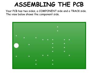
This detailed guide provides step-by-step instructions for assembling the BalloonSat Mini project, including identifying parts, soldering resistors, diode, headers, IC socket, relay, capacitor, voltage regulator, LED, I/O port, DB-9 connector, battery snap, and testing the circuit for quality and functionality. Learn how to avoid shorts, check voltage, and program the PICAXE-08M2 microcontroller for a successful build.

E N D
Now Test! • Check quality of solders • Look for a short between terminals in the battery snap • Look for +5 volts on the IC socket • Programming test
Set a DMM to measure continuityYou don’t want to hear it ring!
Set DMM to DC Volts (20 V scale)Want to measure 4.75 to 5.25 volts • +5 volts on pin #1 and ground on pin #8
Programming Test • Correct mode: PICAXE-08M2 • Correct Serial Port • Two line program