Download
1 / 23
230 likes | 251 Views
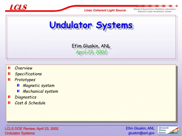
Undulator Line Design Liz Moog, Advanced Photon Source April 24, 2002. Requirements for individual undulators Radiation considerations Undulator magnetic design and model calculations Initial results from prototype Controls. Cell structure of the LCLS undulator line. 421. 187. 3420.

E N D
Undulator Line DesignLiz Moog, Advanced Photon SourceApril 24, 2002 • Requirements for individual undulators • Radiation considerations • Undulator magnetic design and model calculations • Initial results from prototype • Controls Liz Moog, ANL / APS
Cell structure of the LCLS undulator line 421 187 3420 UNDULATOR 11055 mm Horizontal Steering Coil Vertical Steering Coil Beam Position Monitor X-Ray Diagnostics Quadrupoles Liz Moog, ANL / APS
Requirements for individual undulator segments - 1 • Trajectory straightness • Beam will be centered at the beam position monitors between undulators; trajectory must remain straight in undulators • Allowed x and y deviation is 2 µm (0.2% increase in gain length) • At 14.35 GeV, this corresponds to a second integral of the field of 9600 G-cm2 (or, at 4.5 GeV, 3000 G-cm2) • Magnetic measurement reproducibility for second integral is now ~ 1000 G-cm2 Liz Moog, ANL / APS
Requirements for individual undulator segments - 2 • Reduction in first-harmonic radiation at zero angle • Allowed reduction is 4%. • Corresponds to 1.1% increase in gain length • In practice, the reduction can be calculated by comparing to the best of the undulators • Phase deviation • Allowed deviation from the design value (2π * integer) is 10° • Corresponds to 1.7% increase in gain length • Measurement reproducibility is now 0.5° Liz Moog, ANL / APS
Requirements for individual undulator segments - 3 • Vertical alignment • Undulator midplane must be determined (and aligned) to 50 microns vertically • 50 microns displacement gives ~ 10° in phase slippage Combined effect of these errors is 3% growth in power gain length Requirements have all been met in the APS FEL Liz Moog, ANL / APS
Requirements for individual undulator segments - 4 • Uniformity of magnetic field strength • Error in magnetic field strength in an undulator by ∆B/B = 1.5 x 10⁻⁴ gives a phase error of 10° • Simulations using the code RON agree, finding significant change in gain when variation reached 1.3 x 10⁻⁴ • This is error in B of 1.7 G (or gap error of 1.2 µm) • May impose requirements on temperature uniformity along the undulator line Liz Moog, ANL / APS
Undulator Ends • Undulator ends will be tuned to keep trajectory straight • Sequence of end pole field strengths near 1/4, -3/4, 1, -1 • No offset and no angle kick • Ends will be tuned for proper phase • For APS undulators, phase can be adjusted by ±38° by tuning • Alignment tolerance for installation is 1 mm • Remote adjustment of phase will be possible Liz Moog, ANL / APS
Break lengths Liz Moog, ANL / APS
Radiation considerations - What damages magnets? • Bending magnet irradiation (~40 keV photons), up to 280 Mrad: no effect* • 60Co (1.17 MeV photons), up to 700 Mrad: no effect* • 17 MeV electrons: at 260 Mrad, 9% remanence loss† • Above a few MeV, the shower produced includes both electrons and photons, independent of whether the initial particle was electron or photon * Alderman, et al., ANL-APS LS-290. † Okuda, et al., NIM B 94 (1994) 227. Liz Moog, ANL / APS
Radiation considerations - What damages magnets? • Radiation-induced demagnetization has been seen at both ESRF (6 GeV) and APS (7 GeV), so the 14.35 GeV LCLS should be quite capable of damaging magnets • There is no space to pile Pb shielding upstream of each undulator. Liz Moog, ANL / APS
How can likelihood of radiation damage be reduced? • Controllable factors : • Magnet grade - i.e., intrinsic coercivity iHc • Lower coercivity of the magnet correlates with greater sensitivity to radiation damage (Van Vaerenbergh et al., RADECS 99 proceedings; Ikeda and Okuda, NIM A407 (1998) 439) • Magnetic environment - i.e. local demagnetizing field in the magnet block • Correlation found between stronger demagnetizing field during irradiation and greater likelihood of demagnetizing (Brown and Cost, J. Appl.Phys 63 (1988) 3537, and IEEE Trans Magn. 25 (1989) 3117) Liz Moog, ANL / APS
Magnet grades Data sheet from Shin-Etsu Liz Moog, ANL / APS
Calculated characteristics of magnetic model • Period is 30 mm • At 6 mm gap, • Bpeak=13897 G • Beff = 13481 G (13250 G desired) • Keff = 3.776 (3.71 desired) • force per pole = 258 N (or 58 lbs.) • transverse position where ∆B/B=1.3x10-4 is at 2.9 mm Liz Moog, ANL / APS
Initial results from prototype undulator • Actual field strength is stronger than predicted by model calculation • Keff = 3.91 instead of 3.78 • Gap of undulator will be adjusted (by about 0.3 mm) to compensate Liz Moog, ANL / APS
Controls - 1 • Controls will be based on EPICS and will build on existing controls at APS • Where possible, integrate with commercial off-the-shelf components • Support multiple devices on single fieldbus network • Custom design when needed • APS-designed valve controller • Vacuum interlocks • Low frequency data collection for vacuum controls • Short-haul wireless technology (e.g. Bluetooth) may integrate well Liz Moog, ANL / APS
Controls - 2 • High motor count dictates dense control scheme; encoders assumed • Diagnostics • High speed cameras and frame grabbers (>120 Hz) should be available in the near-term • PC based analysis is becoming industry norm • Allows rapid analysis and easy upgrades • Magnet power supplies controlled via fieldbus • Phase correctors use PZT stages controlled with commercial hardware - few stages per controller • Investigate custom hardware? Liz Moog, ANL / APS