Download
1 / 70
700 likes | 868 Views
Networking Components:. 3.06 Other Networking Devices. These are devices that will connect you to a wireless network or a WAN environment. These devices are only quickly mentioned here because they appear again in the chapters on WAN and remote connectivity. Wireless Access Points

E N D
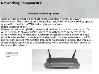
Networking Components: 3.06 Other Networking Devices These are devices that will connect you to a wireless network or a WAN environment. These devices are only quickly mentioned here because they appear again in the chapters on WAN and remote connectivity. Wireless Access Points Wireless access points (WAPs) are network devices that can be connected to the wired network to allow a wireless client to pass through to get access to the wired network and its resources. A wireless access point also is known as a cell, which is a device that transmits and receives radio frequencies between the PCs and network devices with wireless transmitters connected to them. The wireless access point is connected to a physical cable, which connects the WAP device to the rest of the network.
Networking Components: 3.06 Other Networking Devices Modems There are other forms of networking devices beyond the typical network card; for instance, modems can be used to communicate with other systems across the public switched telephone network (PSTN). They are used to convert digital data from the PC to analog transmission so that the information can be transmitted over the analog phone lines. The modem on the receiving end is designed to convert the analog signal to a digital format readable by the system. CSU/DSU A channel service unit/data service unit (CSU/DSU) is either one device or a pair of devices that allows an organization to get a very-high-speed WAN connection from the telephone company, such as a T1 or T3 link. The CSU is used at the business end to get the connection to the WAN, and the DSU may be used at the provider’s end to allow the CSU to connect.
Networking Components: 3.06 Other Networking Devices ISDN The Integrated Services Digital Network (ISDN) is a communication standard for sending voice and data over normal telephone lines or digital telephone lines. In order to connect to the ISDN lines, a system will need an ISDN modem, which doesn’t really act like a modem because, whereas a modem converts digital data to analog, the ISDN modem carries digital data from one digital system to another, and so it really is acting as a terminal adapter connecting you to the ISDN lines. There are two popular types of ISDN connections: Basic rate interface (BRI) This is a 128 Kbps connection that is made up of two 64 Kbps channels (known as B-channels) and one 16 Kbps control channel (known as a D-channel). Primary rate interface (PRI) This is a 1.55 Mbps connection that is made up of twenty-three 64 Kbps channels (B-channels) and one 64 Kbps D-channel for signaling and control information.
Networking Components: 3.06 Other Networking Devices Wiring Distribution Plenum vs. Nonplenum For the Network+ exam you need to be familiar with the term plenum. Plenum refers to the space between the ceiling tiles and the floor located above them. This space is typically used to route power and network cables. It is important to use plenum grade cables in this space because if there is a fire and you are not using plenum grade cables, a toxin is given off that could be carried throughout the building, causing harm to individuals. Plenum-grade cabling uses a low-toxicity material for the jacket of the cable in case of fire.
Networking Components: 3.06 Other Networking Devices Patch Panel Most companies have network jacks located in the walls that allow systems to connect to the network. These jacks have cables connected to them that are then routed a long distance to a patch panel in a server room. The patch panel then has a patch cable that connects to the front of the patch panel and a port on a switch. When a computer connects to the network jack in the wall, the patch cable is used to map that system to the port on the switch. The concept of the patch panel allows ease of administration and flexibility in moving systems from one switch to another without visiting the workstation. Figure 3-28 displays a patch panel.
Networking Components: 3.06 Other Networking Devices Cross Connects, MDF, and IDF When wiring the network you will typically have the outside line coming into the building connect to a panel; this panel is known as the main distribution frame, or MDF. From the MDF you would typically connect to other panels, known as intermediate distribution frames (IDFs), which is what the workstations connect to. This hierarchy of MDF and IDF panels allows greater flexibility when rearranging the network at a later time.
Networking Components: 3.06 Other Networking Devices Cross Connects, MDF, and IDF When wiring the network you will typically have the outside line coming into the building connect to a panel; this panel is known as the main distribution frame, or MDF. From the MDF you would typically connect to other panels, known as intermediate distribution frames (IDFs), which is what the workstations connect to. This hierarchy of MDF and IDF panels allows greater flexibility when rearranging the network at a later time.
Networking Components: 3.06 Other Networking Devices A typical example of how the MDF and IDFs are used is that the MDF would connect to the cable coming from outside the building. Then there may be a separate IDF panel representing each floor in the building, with the workstations on a particular floor connecting to the panel associated with that floor. The patch cable that connects to the patch panel is called a horizontal cross-connect (HCC) cable. The cable that connects the MDF to the IDFs is called the vertical cross-connect (VCC) cable.
Networking Components: 3.06 Other Networking Devices Certification Summary :In this chapter, you learned about some of the popular networking devices that are used on networks to allow systems to communicate on the network. The first of those devices is the network card. The network card is responsible for converting parallel data that is transmitted through the computer’s bus to a serial bit stream to be sent on the wire. The network card uses a transceiver. Transceivers constitute that portion of the network interface that actually transmits and receives electrical signals across the transmission media and connects to the media. There are two types of transceivers: built in and external. The NIC usually has a built-in transceiver for twisted-pair and thinnet, but thicknet typically uses an external transceiver.
Networking Components: 3.06 Other Networking Devices The network card uses the MAC address burned into the card by the manufacturer as an identifier to determine where the packet is destined and where it came from. The system does this by adding the source MAC address and destination MAC address to the packet, which is read by networking devices to determine where the packet needs to go. There are a few popular layer-1 devices, such as hubs, repeaters, and MAUs. Remember that these devices are considered layer 1 because they work with the electrical signals. Any data that reaches a layer-1 device will be sent to all ports on the device. A repeater is responsible for regenerating the electrical signal so that the signal may travel a greater distance
Networking Components: 3.06 Other Networking Devices A MAU is used in a Token Ring environment and regenerates the signal with each system connected to the MAU. When connecting MAUs, you will need to ring out of one MAU and ring in to the second MAU; you will then ring out of the second MAU and ring in to the third MAU. Remember to ring out of the last one and ring in to the first MAU. Bridges and switches are examples of layer-2 devices. A bridge is responsible for filtering network traffic by sending the data only to the network segment where the destination system resides. The bridge builds a bridging table, which has a list of destinations. A switch has replaced the network hub nowadays, and it filters traffic by sending data only to the port on the switch where the destination system is connected. You can increase network performance dramatically by changing your network hubs to switches. A number of switches support VLAN capabilities.
Networking Components: 3.06 Other Networking Devices A VLAN is used to create virtual networks out of ports on one or more switches. When data is broadcast on the VLAN, it is sent only to members of the VLAN, not the entire switch. Systems can communicate only with other systems on their VLAN and cannot communicate with systems on other VLANs without the use of router. Some other popular networking components are routers, gateways, and firewalls. Routers are layer-3 devices that are responsible for sending data from one network to another. A gateway is responsible for converting data from one format to another so that the data can be understood on both sides of the gateway. A firewall is a device that stops traffic from passing through it, protecting private network resources.
Networking Components: 3.06 Other Networking Devices Two-Minute Drill Network Interface Cards: Network interface cards (NICs) function by converting parallel data from the computer to a serial bit stream sent on the network. The computer must have a software driver installed to enable it to interact with the NIC, just as it must for any other peripheral device. The media access control (MAC) address, or hardware address, is a 12-digit number that is used to determine where the data is being sent and where it is coming from. The MAC address also is known as a layer-2 address and looks like 00-0D-60-48-53-9E. A computer bus is the term used for the speed and type of interface the computer uses with various types of interface cards and equipment. Popular bus architectures are ISA, PCI, and PCMCIA for laptops. When you install a network card, you will need to be familiar with what bus slot you will place the card into.
Networking Components: 3.06 Other Networking Devices The network card uses a transceiver to pick up the electrical signals and send electrical signals on the wire. There are two types of transceivers: built in and external. The transceivers for twisted-pair and thinnet usually are built into the network card, whereas the transceiver for thicknet is usually an external one. q When you are configuring the network card, you may need to specify the transfer rate so that it supports the device you are connecting to. You also may need to specify the transceiver you intend to use, the transmission type, and whether to use half duplex or full duplex. Simplex transmissions allow data to be sent in only one direction. Half duplex allows data to be sent and received, but not at the same time. Full duplex allows data to be sent and received at the same time. Hubs, MAU s, and Repeaters Hubs are the central location to which all cabling must connect in most topologies. When exam time comes, remember the difference between an active hub and a passive hub. An active hub contains electronic components to boost the signal. A passive hub does not.
Networking Components: 3.06 Other Networking Devices A multistation access unit (MAU) is a device to which multiple workstations are connected in order to communicate on a Token Ring network. Because the signal gets weaker over distance, repeaters are used to regenerate the signal so that it can continue in its travels. Hubs, MAUs, and repeaters are layer-1 devices. Bridges and Switches: A bridge is used to create multiple segments on the network. The bridge will forward network traffic only to the destination segment and not to all segments, thus acting as a filtering device to improve network performance. A switch filters network traffic by sending data only to the port on the switch where the destination system resides. Switches are replacing hubs, and network administrators who wish to improve network performance should replace their hubs with switches.
Networking Components: 3.06 Other Networking Devices Gateways and Security Devices q A gateway is a device that is used to join dissimilar environments together. q The gateway converts data from one side of the gateway to a format that the other side of the gateway will understand. q A firewall is a device that blocks all network traffic from passing through the firewall in order to protect private network resources. The firewall may be configured to allow selected traffic to pass through. For example, most companies have a web server that publishes their web site, so they will need to allow HTTP traffic to pass through the firewall. Other Networking Devices q Modems are used as remote connectivity devices to connect systems across telephone wires. The modem converts digital signals to analog on the sending computer and converts analog signals to digital on the receiving computer. q CSU/DSU is a network device that allows an organization to connect to a high-speed link such as a T1 or T3. q ISDN is a digital service that is used to connect systems over a digital phone line and to receive transmission rates faster than conventional modems.
Networking Components: 3.06 Other Networking Devices Some switches support virtual LANs (VLANs). A VLAN is a group of ports on the switch that make up their own logical network. Systems on a particular VLAN can communicate only with other systems on the same VLAN unless a router is used. The VLAN also acts as a broadcast domain, because broadcast traffic is sent only to ports in the VLAN where the sender of the broadcast traffic exists. Bridges and switches are layer-2 devices. Routers and Brouters: A router is a layer-3 device that sends data from one network to another using layer-3 address such as an IP address. Routers are used by routable protocols such as IPX/SPX, TCP/IP, and AppleTalk. A brouter is a device that combines a bridge and a router. The brouterwill act as a router for routable protocols but will act as a bridge for nonroutable protocols such as NetBEUI.
4 TCP/IP Fundamentals 4.01 TCP/IP Protocol Suite • IP protocol suite, and each protocol runs on different layers of the Internet model. • Let’s start at the top of this model, which is the application layer. The application layer is responsible for making the network request (sending computer) or servicing the request (receiving computer). For example, when a user submits a request from a web browser, the web browser is responsible for the submission of the request and is running at this layer. When that web request reaches the web server, the web server, running at the application layer, accepts that request. The following are popular application-layer protocols; for more information, see the section “Application- Layer Protocols” in this chapter: • Hypertext Transfer Protocol (HTTP) • Simple Mail Transfer Protocol (SMTP) • Network News Transport Protocol (NNTP) • File Transfer Protocol (FTP)
4 TCP/IP Fundamentals 4.01 TCP/IP Protocol Suite
4 TCP/IP Fundamentals 4.01 TCP/IP Protocol Suite Transport Layer: The next layer under the application layer is the transport layer. The transport layer is responsible for both connection-oriented communication (a session is established) and connectionless communication (a session is not established). When the request comes down from the higher (application) layer, a transport protocol is then chosen. The two transport protocols in TCP/IP are the Transmission Control Protocol (TCP) and the User Datagram Protocol (UDP). Transmission Control Protocol The Transmission Control Protocol (TCP) is responsible for providing connection-oriented communication and ensuring delivery of the data. TCP will make sure that the data reaches its destination by retransmitting any data that is lost or corrupt. TCP is used by applications that require a reliable transport, but this transport has more overhead than a connectionless protocol because of the construction of the session and monitoring and retransmission of any data across that session. Another factor to remember about TCP is that the protocol requires that the recipient acknowledge the successful receipt of data.
4 TCP/IP Fundamentals 4.01 TCP/IP Protocol Suite User Datagram Protocol The User Datagram Protocol (UDP) offers a connection-less: datagram service that is an unreliable “best-effort” delivery. UDP does not guarantee the arrival of datagrams, nor does it promise that the delivered packets are in the correct sequence. Applications that don’t require an acknowledgment of data receipt use UDP. Because of the lack of overhead involved in UDP conversations, it is more efficient than TCP.
4 TCP/IP Fundamentals 4.01 TCP/IP Protocol Suite Internet Layer: After a transport protocol has been selected, which boils down to whether the communication should be connection-oriented or connectionless, the information is passed to the Internet layer to determine who is responsible for the delivery of the information. There are a few protocols that run at the Internet layer; IP, ICMP, and ARP are examples. Internet Protocol The Internet Protocol (IP) provides packet delivery for: protocols higher in the model. It is a connectionless delivery system that makes a “best-effort” attempt to deliver the packets to the correct destination. IP does not guarantee delivery of the packets—that is the responsibility of transport protocols; IP simply sends the data. The IP protocol is also responsible for the logical addressing and routing of TCP/IP and therefore is considered a layer-3 protocol (of the OSI model). The IP protocol on the router is responsible for decrementing (usually by a value of 1) the TTL (time to live) of the packet to prevent it from running around in a “network loop.” Windows operating systems have a default TTL of 128.
4 TCP/IP Fundamentals 4.01 TCP/IP Protocol Suite Internet Control Message Protocol The Internet Control Message Protocol (ICMP) enables systems on a TCP/IP network to share status and error information. You can use the status information to detect network trouble. ICMP messages are capsulated within IP datagrams so that they may be routed throughout a network. Two programs that use ICMP messages are Ping and Tracert. You can use Ping to send ICMP echo requests to an IP address and wait for ICMP echo responses. Ping reports the time interval between sending the request and receiving the response. With Ping, you can determine whether a particular IP system on your network is functioning correctly. You can use many different options with the Ping utility. Tracert traces the path taken to a particular host. This utility can be very useful in troubleshooting internetworks. Tracert sends ICMP echo requests to an IP address while it increments the TTL field in the IP header by a count of 1 after starting at 1 and then analyzing the ICMP errors that are returned. Each succeeding echo request should get one further into the network before the TTL field reaches 0 and an “ICMP time exceeded” error message is returned by the router attempting to forward it. Also note that Internet Group Management Protocol (IGMP) is another Internet layer protocol and is used for multicast applications.
4 TCP/IP Fundamentals 4.01 TCP/IP Protocol Suite Address Resolution Protocol The Address Resolution Protocol (ARP) provides IP address–to–physical address resolution on a TCP/IP network. To accomplish this feat, ARP sends out a broadcast message with an ARP request packet that contains the IP address of the system it is trying to find. All systems on the local network see the message, and the system that owns the IP address for which ARP is looking replies by sending its physical address to the originating system in an ARP reply packet. The physical/IP address combo is then stored in the ARP cache of the originating system for future use. All systems maintain ARP caches that include IP address–to–physical address mappings. The ARP cache is always checked for an IP address–to–physical address mapping before initiating a broadcast. Application-Layer Protocols: Now that you have learned some of the core protocols such as TCP, UDP, and IP in the TCP/IP protocol suite, let’s take a look at some of the application-level protocols that run at the application layer of the TCP/IP Internet model.
4 TCP/IP Fundamentals 4.01 TCP/IP Protocol Suite HTTP and HTTPS: The Hypertext Transfer Protocol (HTTP) is the protocol used on the Internet to allow clients to request web pages from web servers and to allow client interaction with those web servers. HTTP is a stateless protocol, meaning that the web servers are not aware of what a client has or has not requested and cannot track users who have requested specific content. This system does not allow for good interaction with the web server but does allow for retrieving the HTML pages stored on web sites. To aid in tracking client requests, we use cookies—small files stored on the client computer that allow the web server to store data on the client that the client will send back with each request to the server. The Hypertext Transfer Protocol, Secure (HTTPS) allows you to connect to a web site and receive and send content in an encrypted format using the Secure Sockets Layer (SSL). HTTPS is most commonly used on e-commerce sites to allow you to send personal information without worrying that an Internet hacker is viewing this information, especially credit card numbers and other confidential data. You can determine when HTTPS is being used because the address of the web site starts with https:// and not http://, which marks the regular HTTP protocol. Another sign that HTTPS is in use: In Internet Explorer, a lock appears in the status bar of a page; the lock is either closed or locked
4 TCP/IP Fundamentals 4.01 TCP/IP Protocol Suite Network Time Protocol (NTP): The Network Time Protocol (NTP) is used to synchronize the clocks of PCs on a network or the Internet. This is accomplished by configuring a server to be the time server, which then is the server from which all other PCs on the network synchronize their time. On earlier Windows networks, you can manage time synchronization by placing a command in a logon script to synchronize the time on the client with the time server. Use the following command: NET TIME \\computername /SET Newer Microsoft networks, such as Active Directory networks, have the PDC emulator provide the time to all servers and clients automatically, so there is no need to create a logon script for the clients to synchronize the time with the time server. PDC emulators can also retrieve their time from Internet NTP servers. Time servers on the Internet allow you to synchronize your PC’s clock with the exact time kept by atomic clocks. The time synchronization takes into account time zone settings of your operating system and allows you to synchronize with a time server even if it is not set for your local time zone.
4 TCP/IP Fundamentals 4.01 TCP/IP Protocol Suite Network News Transfer Protocol (NNTP): News clients use the Network News Transfer Protocol (NNTP) to send and retrieve news articles to a newsgroup. Newsgroups are typically used as a place for users to post questions and answers on a particular topic area (called a newsgroup). NNTP uses TCP to send and receive news articles. NNTP allows the submission and retrieval of only the news articles that have not previously been sent or retrieved. Simple Mail Transfer Protocol (SMTP): The Simple Mail Transfer Protocol (SMTP) is used to send or route mail over a TCP/IP network such as the Internet. Most e-mail server products support SMTP in order to send e-mail out of the corporation and onto the Internet. Post Office Protocol 3 (POP3): The Post Office Protocol, version 3 (POP3) is the Internet protocol used to retrieve e-mail from a mail server down to the POP3 client. The e-mail is “popped” or downloaded to the client after the client has been authenticated to its mailbox. POP3 has limited capabilities as far as folder support is concerned. A POP3 client supports only an inbox, an outbox, sent items, and deleted items. If additional folder support is required, you would need to use an IMAP4 client.
4 TCP/IP Fundamentals 4.01 TCP/IP Protocol Suite Internet Message Access Protocol 4 (IMAP4) The Internet Message Access Protocol, version 4 (IMAP4) is another protocol similar to POP3 that allows clients to retrieve messages from a mail server. IMAP4 allows additional folders other than the four basic ones provided with POP3. For example, you can use an IMAP4 client to connect to public folders stored on an Exchange Server.
4 TCP/IP Fundamentals 4.01 TCP/IP Protocol Suite Simple Network Management Protocol (SNMP): The Simple Network Management Protocol (SNMP) is an Internet standard that provides a simple method for remotely managing virtually any network device that supports SNMP. A network device can be a network card in a server; a program or service running on a server; or a network device such as a hub, switch, or router. The SNMP standard defines a two-tiered approach to network device management: a central management system and the management information base (MIB) located on the managed device. The management system can monitor one or many MIBs, allowing for centralized management of a network. From a management system, you can see valuable performance and network device operation statistics, enabling you to diagnose network health without leaving your office. The goal of a management system is to provide centralized network management.
4 TCP/IP Fundamentals 4.01 TCP/IP Protocol Suite • Any computer running SNMP management software is referred to as a management system. For a management system to be able to perform centralized network management, it must be able to collect and analyze many things, including the following: • Network protocol identification and statistics • Dynamic identification of computers attached to the network (referred to as discovery). • Hardware and software configuration data. • Computer performance and usage statistics • Computer event and error messages • Program and application usage statistics
4 TCP/IP Fundamentals 4.01 TCP/IP Protocol Suite File Transfer Protocol (FTP): The File Transfer Protocol (FTP) is a TCP/IP protocol that exists to upload and download files between FTP servers and clients. Like Telnet and Ping, FTP can establish a connection to a remote computer using either the hostname or the IP address and must resolve hostnames to IP addresses to establish communication with the remote computer. When TCP/IP is installed on the system, there is an FTP utility available, but there are also a number of third-party graphical user interface (GUI) FTP clients available for all operating systems. If you use FTP a great deal, a GUI FTP client could save you a lot of time and frustration in dealing with FTP commands. Trivial File Transfer Protocol (TFTP): The Trivial File Transfer Protocol (TFTP) is a simple protocol compared to FTP that supports only reading and writing to files and does not support features such as listing directory contents and authentication. TFTP uses UDP as the transport protocol, as opposed to FTP, which uses TCP. TFTP is typically used to boot diskless workstations. Secure File Transfer Protocol (SFTP): The Secure File Transfer Protocol (SFTP) is an interactive file transfer protocol similar to FTP, but it encrypts all traffic between the SFTP client and the SFTP server. SFTP supports additional features such as public key authentication and compression. Unlike TFTP, SFTP does support a number of commands in its interactive shell such as listing directory contents, creating directories, downloading files, and uploading files. Telnet: Telnet is a terminal emulation protocol that allows a client to run or emulate the program running on the server. A number of devices allow you to telnet into the device and perform remote administration of the network device using the command set available to the Telnet session.
4 TCP/IP Fundamentals 4.01 TCP/IP Protocol Suite Secure Shell (SSH): The Secure Shell (SSH) is a program used to create a shell, or session, with a remote system. Once the remote session is established, the client can execute commands within this shell and copy files to the local system. SSH has a major purpose in life, and that is to support remote shells with support for secure authentication and encrypted communication. Secure Copy Protocol (SCP): The Secure Copy Protocol (SCP) is responsible for copying files from a remote server to the local system over a secure connection, ensuring that data in transit is kept confidential. A number of SCP products use an SSH connection to ensure the security of the secure copy operation. Lightweight Directory Access Protocol (LDAP): The Lightweight Directory Access Protocol (LDAP) is the TCP/IP protocol for directory service access that is supported by all the principal directory services, such as Novell’s eDirectory and Microsoft’s Active Directory. LDAP is a protocol that allows LDAP clients to connect to the network database, or directory, and query the database for information about its objects, such as user accounts and printers. For example, a user on the network could find out the phone number of another user by using the LDAP protocol. Line Printer Daemon (LPD) and Line Printer Remote (LPR): The line printer daemon (LPD) is a printer protocol, or service, installed on the print server to allow line printer remote (LPR) clients to send print requests to the print server. When LPD receives the print request, it stores the print request in a queue until the printer becomes available. Now that you are acquainted with some of the core protocols of TCP/IP and some of the application-layer protocols that run on top of TCP/IP, let’s take a look at the possible scenarios involving TCP/IP protocols and services and their appropriate solutions.
4 TCP/IP Fundamentals 4.02 TCP/IP Fundamentals TCP/IP Settings: TCP/IP is a protocol that requires a little bit of knowledge to configure the systems properly. When you configure TCP/IP, you are required to know the settings for the IP address, subnet mask, and default gateway. IP Address The IP address is a 32-bit value that uniquely identifies the system on the network (or the Internet). An IP address looks similar in appearance to 192.168.1.15. There are four decimal values in an IP address separated by periods (.). Each decimal value is made up of 8 bits (1s and 0s), and there are four decimal values, so 8 bits times 4 equals the 32-bit address. Since each of the decimal values is made up of 8 bits (for example, the 192), we refer to each of the decimal values as an octet. There are four octets in an IP address. It is very important to understand that the four octets in an IP address are divided into two parts—a network ID and a host ID. The subnet mask determines the number of bits that make up the network ID and the number of bits that make up the host ID. Let’s see how this works.
4 TCP/IP Fundamentals 4.02 TCP/IP Fundamentals Subnet Mask: When looking at a subnet mask, if there is a 255 in an octet, then the corresponding octet in the IP address is part of the network ID. For example, if I had an IP address of 192.168.1.15 and a subnet mask of 255.255.255.0, the first three octets would make up the network ID and the last octet would be the host ID. The network ID assigns a unique address to the network itself, while the host ID uniquely identifies the system on the network. You can see in Table 4-1 that the network ID (shown with an “N”) is 192.168.1, and the host ID is the last octet with a value of 15. This means that this system ison the 192.168.1 network and any other system on the same network will have the same network ID. To use a different example, if I had a subnet mask of 255.0.0.0, it would mean that the first octet of the IP address is used as the network ID portion, while the last three octets are the host ID portion of the IP address. So what is the purpose of the subnet masks? Or better yet, why do we have a subnet mask that breaks the IP address into a network ID part and a host ID? The reason is so that when a system such as 192.168.1.15, with a subnet mask of 255.255.255.0, sends a piece of data to 192.198.45.10, the sending system first needs to determine whether the target computer exists on the same network or not. It does this by comparing the network IDs (Table 4-2); if the network IDs are the same, then both systems exist on the same network and one system can send to the other without the use of a router. If the systems exist on different networks, the data will need to be passed to the router so that the router can send the data to the other network.
4 TCP/IP Fundamentals 4.02 TCP/IP Fundamentals
4 TCP/IP Fundamentals 4.02 TCP/IP Fundamentals Default Gateway: When your system wants to send data to another system on the network, it looks at its own network ID and compares that to the destination system’s IP address. If it appears that they both have the same network ID, the data is sent directly from your system to the destination system. If the two systems are on different networks, your system must pass the data to the router so that the router can send the data to the destination system’s router. The question is now, how does your system know who the router is? The answer is “that is what the default gateway is.” The default gateway is the IP address of the router that can send data from your network. In order to communicate on the Internet, your system will need to be configured with an IP address, a subnet mask, and a default gateway. If you need to communicate only with other systems on your network, you will need only an IP address and a subnet mask. TCP/IP Addressing: This section will introduce you to the binary representation of an IP address and ensure that before you move onto the next chapter (on subnetting) you feel comfortable with converting binary values to decimal and address classes.
4 TCP/IP Fundamentals 4.02 TCP/IP Fundamentals Address Classes Every IP address belongs to a distinct address class. The Internet community defined these classes to accommodate networks of various sizes. The class to which the IP address belongs initially determines the network ID and host ID portions of the address, along with the number of hosts that are supported on that network. The different class addresses are named class A, class B, class C, class D, and class E. This section details each class of addresses. Class A Addresses A class A address has a default subnet mask of 255.0.0.0, which means that the first octet is the network ID and the last three octets belong to the host ID portion of the address. Each octet can contain 256 possible values (0–255), so a class A address supports 16,777,216 hosts on the network (256 × 256 × 256). Actually, there are only 16,777,214 valid addresses to use on systems, inasmuch as there are two addresses on each IP network you are not allowed to assign to systems because they are reserved. These are the addresses with all host bits set to 0s (the network ID) and all host bits set to 1s (the broadcast address). So with a class A address, you will not be able to assign n.0.0.0 or n.255.255.255 (where n is your network ID) to any hosts on the network. You can always identify a class A address, because the value of the first octet falls between the numbers 1 and 126. Actually, an address that starts with 127 is a class A address as well, but you are not allowed to use any address that starts with 127, because it is reserved for the loopback address (more on the loopback address later). For example, the IP address 12.56.87.34 is a class A address because the first octet is 12, which falls in the range 1–126. Class A addresses have an IP address in which the first octet is between 1 and 126. Class A addresses also have a default subnet mask of 255.0.0.0. Class B Addresses Class B addresses have a default subnet mask of 255.255.0.0, which means that the first two octets are the network ID and the last two octets are the host ID portion of the address. This means that we can have 65,536 hosts (256 × 256) on the network. Oh, but wait! Don’t forget to take off the two illegal addresses, so that gives us 65,534 addresses that can be assigned to hosts on the network. Due to the number of hosts that are supported on a class B address, you usually find that a medium-sized company has a class B address. You can identify a class B address because the first octet starts with a number that falls between 128 and 191. Class B addresses have an IP address in which the value of the first octet is between 128 and 191. Class B addresses have a default subnet mask of. 255.255.0.0
4 TCP/IP Fundamentals 4.02 TCP/IP Fundamentals Class C Addresses Class C addresses have a subnet mask of 255.255.255.0, which means that the first three octets are the network ID and the last octet is the host ID. Having only one octet as the host ID means that a class C address can support only 254 hosts (256 – 2) on the network. You can identify a class C address because it has a value for the first octet that ranges between 192 and 223. For example, an IP address of 202.45.8.6 is a class C address because 202 falls between 192 and 223. You also know that this system has a subnet mask of 255.255.255.0 because it is a class C address. Class C addresses have an IP address in which the value of the first octet is between 192 and 223. In addition, class C addresses have a default subnet mask of 255.255.255.0. Class D Addresses Class D addresses are used for special types of applications on the network known as multicasting applications. Multicasting applications send data to a number of systems at the same time by sending data to the multicast address, and anyone who has registered with that address will receive the data. A multicast address is what class D addresses are used for, so you will not be assigning them specifically to hosts on the network for normal network communication. Class D addresses have a value on the first octet that ranges from 224 to 239. With that many ranges, class D has the potential for 268,435,456 unique multicast groups that users can subscribe to from a multicast application.
4 TCP/IP Fundamentals 4.02 TCP/IP Fundamentals Class E Addresses The funny thing about class E addresses is that they were designed for experimental purposes only, so you will never see a class E address on a network. Class E addresses have a first octet with a value that falls in the range of 240–247. Loopback Address You have learned that you are not allowed to have a host assigned an IP address that has a value of 127 in the first octet. This is because the class A address range of 127 has been reserved for the loopback address. The loopback address is used to refer to the local system, also known as the localhost. If you want to verify that the TCP/IP software has initialized on the local system even though you may not have an IP address, you may ping the loopback address, which is typically referred to as 127.0.0.1.
4 TCP/IP Fundamentals 4.02 TCP/IP Fundamentals • Private Addresses • Another type of address you need to be aware of is what is known as a private address. A private address is an address that can be assigned to a system but cannot be used for any kind of Internet connectivity. The private addresses are non-routable addresses, so any system using them will not be able to function off the network. The following are the three address ranges that are private: • 10.0.0.0–10.255.255.255 • 172.16.0.0–172.31.255.255 • 192.168.0.0–192.168.255.255 • Illegal Addresses • There are a few IP addresses that are illegal to assign to hosts on the network. You might wonder why a class C address can have only 254 hosts and not 256, as would seem more likely, since an 8-bit number can have 256 possible values. The reason for this seeming discrepancy is that two of the addresses are lost from the available host pool. The first is an address that has all bits set to 0s in the host ID, which signifies the network ID of the network. The second is an address that has all bits set to 1s in the host ID, which signifies the broadcast address for the network. • So, for example, in the class C network 200.158.157.x, the addresses 200.158.157.0 (the network ID) and 200.158.157.255 (the broadcast address) are not available to hosts, reducing the available number of hosts from 256 to 254.
4 TCP/IP Fundamentals 4.03 TCP/IP Addressing • Addressing Schemes • When sending data on the network, there are different ways that the data can be sent to the destination. The data can be sent to a unicast address, a broadcast address, or a multicast address. The following outlines the difference between unicast, broadcast, and multicast: • UnicastIs the sending of information to one system. With the IP protocol • this is accomplished by sending data to the IP address of the intended destination system. • Broadcast Is the sending of information to all systems on the network. Data • that is destined for all systems is sent by using the broadcast address for the network. An example of a broadcast address for a network is 192.168.2.255. • The broadcast address is determined by setting all host bits to 1 and then converting the octet to a decimal number. • Multicast Is the sending of information to a selected group of systems. • Typically this is accomplished by having the systems subscribe to a multicast address. Any data that is sent to the multicast address is then received by all systems subscribed to the address. Most multicast addresses start with 224.x.y.z and are considered class D addresses.
4 TCP/IP Fundamentals 4.02 TCP/IP Fundamentals IPv6 Our entire discussion so far about TCP/IP is based on version 4 of TCP/IP, known as IPv4. The use of TCP/IP over the years has far exceeded expectations, and we are running out of IP addresses. For that reason, TCP/IP has been redesigned and the new version is IP version 6 (IPv6). There are major changes to IPv6 from what we know of IPv4. For starters, IPv4 uses a 32-bit address scheme, while IPv6 will use a 128-bit address scheme. This will give us an insane number of unique possible addresses—3.4 × 1038 to be exact (2128)! This is a huge improvement over 232=4 billion unique addresses with IPv4. An IPv6 address will no longer use four octets. The IPv6 address is divided into eight hexadecimal values that are separated by a colon (:) as shown in the following example: 65b3:b834:45a3:0000:0000:762e:0270:5224
4 TCP/IP Fundamentals 4.03 TCP/IP Addressing TCP/IP Ports: An application or process uses a TCP/IP port as an identifier for that application running on a system. When you send data from one computer to another, you send data to the port used by that application. client applications usually run on ports over 1024. Port numbers that are used by servers are known as well-known ports (under 1024), whereas port numbers over 1024 used by client applications are known as dynamic ports. They are called dynamic ports because many times the port is selected at runtime by the application
4 TCP/IP Fundamentals 4.03 TCP/IP Addressing
4 TCP/IP Fundamentals 4.04 TCP/IP Configuration Concepts TCP/IP Configuration Concepts:You have learned what an IP address, a subnet mask, and a default gateway are used for, and you have learned all about the binary form of addressing, including class addresses. In this section, you will learn to configure TCP/IP on a client system both manually and as a DHCP client. Configuring a system manually is not the best approach to take on a network for a number of reasons: Workload The amount of work involved in manually configuring each system on the network is too much for any network administrator. Typos The potential for human error is great when inputting the parameters on multiple systems simply due to the fact that it is such a laborious task. It is also very easy to assign a duplicate address on the network, which would result in an error. Change management It is very hard to implement major changes to your IP infrastructure when you are manually configuring systems. For example, a change to a router address would require a lot of time to update the default gateway entry on the clients.
4 TCP/IP Fundamentals 4.04 TCP/IP Configuration Concepts Dynamic Host Configuration Protocol (DHCP) Configuring IP addressing on a large TCP/IP-based network can be a nightmare, especially if machines are moved from one network to another frequently. The Dynamic Host Configuration Protocol (DHCP) can help with the workload of configuring systems on a network by assigning addresses to systems on boot-up automatically. The process of dynamically assigning IP addresses is managed via a DHCP server. The DHCP server is configured with a set of usable IP addresses, called a scope. The scope can also include the subnet mask, IP addresses of the default gateway, DNS servers, WINS servers, and other necessary addresses. When a PC comes online and is set up to use a DHCP server, it requests an IP address by transmitting a broadcast request packet looking for any DHCP servers on the network (known as DHCP Discovery). The DHCP server responds with an offer containing an IP address that the client can lease (known as the DHCP Offer).
4 TCP/IP Fundamentals 4.04 TCP/IP Configuration Concepts The client then accepts the offer by sending a request message for that address from the DHCP server (known as the DHCP Request), and then the server responds with an acknowledgment to the client that it has that address and additional settings for the lease time (known as the DHCP ACK). The DHCP server marks the IP address in its database as being in use so that it is not assigned again. When configuring the DHCP server, you will need to configure a scope with the following settings: IP addresses The DHCP server issues an IP address to each DHCP client system on the network. Each system connected to a TCP/IP-based network is identified by a unique IP address. As you learned in this chapter, the IP address consists of four 8-bit octets separated by periods. The IP address is normally shown in dotted-decimal notation—for example, 192.10.24.62. Subnet mask The IP address actually consists of two parts: the network ID and the host ID. The subnet mask is used to identify the part of the IP address that is the network ID and the part that is the host ID. Subnet masks assign 1s to the network ID bits and 0s to the host ID bits of the IP address. Default gateway A default gateway is required when the client system needs to communicate outside its own subnet. Normally, the default gateway is a router connected to the local subnet, which enables IP packets to be passed to other network segments.
4 TCP/IP Fundamentals 4.04 TCP/IP Configuration Concepts Scope Options: A DHCP scope is the range of IP addresses and additional options that the DHCP server will hand out to the DHCP clients on the network. As previously mentioned, the IP address and subnet mask are required items that the DHCP scope must include. Another requirement in the scope is the lease duration. It specifies how long a DHCP client can use an IP address before it must renew it with the DHCP server. This duration can be set for an unlimited time period or for a predetermined time period. You have the option of configuring a scope to reserve a specific IP address for a DHCP client or even for a system on the network that is not DHCP enabled. Servers Several versions of Windows server products support having DHCP server capabilities, including Windows Server 2003 and Windows Server 2008. The main factor to consider if you have multiple subnets is that your routers must comply with RFC 1542 so that a DHCP server can receive the broadcast message from a client. It is wise to keep in mind that, if your DHCP server goes down and your DHCP clients cannot renew their lease, the clients will most likely not be able to access network resources. One of the benefits of using multiple DHCP servers is redundancy. Redundancy can prevent your network from going down. If you decide to use multiple DHCP servers, you should place them on different subnets to achieve a higher degree of fault tolerance in case one of the subnets becomes unavailable. You can manage multiple servers on different subnets with the DHCP Console, the graphical utility used to maintain and configure DHCP servers in Windows.
4 TCP/IP Fundamentals 4.04 TCP/IP Configuration Concepts • Supported Clients • The following operating systems can perform as DHCP clients on your network: • Windows clients such as Windows 2000, XP, Vista n Windows servers such as Windows 2000 Server, Windows Server 2003, and Windows Server 2008 • Older Microsoft clients such as DOS (with network client software loaded), • Windows 3.11, and Windows 9x clients. • Non-Microsoft operating systems such as Linux Of course, DHCP clients are not limited to Microsoft operating systems. Any system that conforms to RFC 1541 can be a DHCP client. For example, you can have a UNIX, Linux, or Novell NetWare client on the network that obtains an address from your DHCP server as well.
4 TCP/IP Fundamentals 4.04 TCP/IP Configuration Concepts APIPA Windows clients support a feature known as automatic private IP addressing (APIPA), which is a feature that provides that, when a Windows client boots up and cannot contact a DHCP server, it will configure itself automatically with a 169.254.x.y address. If there is something wrong with the DHCP server and all the systems on the network cannot obtain an address from the DHCP server, the clients will all assign themselves an address within the 169.254 address range and then be able to communicate with one another. APIPA does not assign a default gateway, so you will be unable to access resources on a remote network and the Internet—but you can still communicate with systems on your network. When troubleshooting to find out why a machine cannot communicate on the network, watch for systems that have the 169.254.x.y address range because it means they could not find a DHCP server. Boot Protocol The Boot Protocol, known as BOOTP, is used by diskless workstations. When a diskless workstation boots, it does so using an EEPROM on the network card to allow it to load basic drivers and connect to the network by obtaining an IP address automatically. A BOOTP server, similar to a DHCP server, assigns the diskless workstation an address for the network to allow it to participate on the network. You will see the term BOOTP a lot when it comes to DHCP and routers; a BOOTP-enabled router will allow the DHCP broadcast to cross the router so that a DHCP server can be found on the other side of the network.