General Electronics Thyristor Training
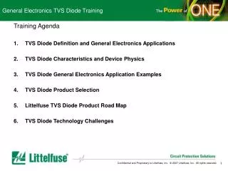
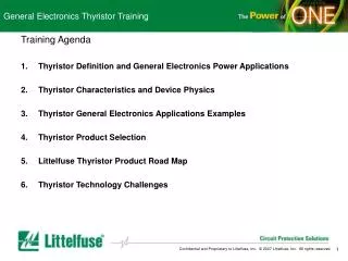
General Electronics Thyristor Training. Training Agenda Thyristor Definition and General Electronics Power Applications Thyristor Characteristics and Device Physics Thyristor General Electronics Applications Examples Thyristor Product Selection Littelfuse Thyristor Product Road Map

General Electronics Thyristor Training
E N D
Presentation Transcript
General Electronics Thyristor Training Training Agenda • Thyristor Definition and General Electronics Power Applications • Thyristor Characteristics and Device Physics • Thyristor General Electronics Applications Examples • Thyristor Product Selection • Littelfuse Thyristor Product Road Map • Thyristor Technology Challenges
General Electronics Thyristor Training Section 1 Thyristor Definition and General Electronics Power Applications • Thyristor Definition • A semiconductor switch whose bi-stable action depends upon P-N-P-N regenerative action • Thyristor Technology for Power Applications in the General Electronics Segment • Thyristors used for phase control • Thyristors used as AC static switches and relays • Thyristors used for lighting systems • Standards Related to Thyristor • IEC 60092-304 {Ed.3.0} • IEC 60700-1 {Ed.1.1} • IEC 60747-6-3 {Ed.1.0} • IEC/TR 60919-1 {Ed.2.0} • IEC 61643-341 {Ed.1.0} • IEC 61803 {Ed.1.0}
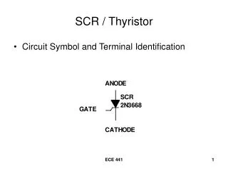
Thyristor Definition and General Electronics Thyristor Definition • A semiconductor switch whose bi-stable action depends upon P-N-P-N regenerative action. • Littelfuse devices included in the Thyristor family:
Thyristor Definition and General Electronics Thyristor Technology in the General Electronics Segment • Phase Control • In these applications, thyristors are used to control the magnitude of average voltage or energy being delivered to a load. • Due to high-volume production techniques, thyristors are now priced so that almost any electrical product can benefit from electronic control. • AC Static Switches and Relays • In these applications, thyristors are used to open or close a circuit or isolate a load. • Since SCRs and the triacs are bistable devices, one of their broad areas of application is in the realm of signal and power switching. • Lighting Systems • One of the many applications for thyristors is in fluorescent lighting ballasts. • Standard conventional and circular fluorescent lamps with filaments can be ignited easily and much more quickly by using thyristors instead of a mechanical starter switch. • The Sidac device is also widely used in flash ignition circuits.
Thyristor Definition and General Electronics Thyristor Standards
General Electronics Thyristor Training Section 2 Thyristor Characteristics and Device Physics • Ratings, Specifications, and Characteristics • Electrical characteristics • Main terminal characteristics • Thyristor turn-on mechanisms • Gate characteristics • Current holding and latching • Turn-on and turn-off time • Dynamic characteristics (di/dt, dV/dt) • Maximum ratings • Peak surge (non-repetitive) on-state Current • Thermal characteristics • Junction temperature • Device Construction and Basic Operation • SCR PNPN operation • Triac PNPN operation • Sidac PNPN operation • Diac NPN operation
Thyristor Characteristics and Device Physics Electrical Thyristor Characteristics Anode-to-Cathode Characteristics • Forward characteristics: • Blocking state • Avalanche region • Breakover point • Negative resistance region • Conducting state • Holding current point • Reverse characteristics: • Blocking region • Avalanche region Critical parameters • IT (On-state Current) • VRRM (Repetitive Peak Reverse Voltage) • VDRM (Repetitive Peak Off-state Voltage) • IH (Holding current) • IGT (Gate Trigger Current) Caution About Gate Current and Voltage • Gate current must be limited to the rated value to avoid damage to device • Reverse gate voltage must be limited to the rated value to avoid damage to device
Thyristor Characteristics and Device Physics Electrical Thyristor Characteristics Gate Characteristics A Thyristor can be gated or triggered to the ON state by applying a small signal between the gate and the cathode. The trigger source is a DC voltage and the gate current must be limited by a series resistor. Typical gate trigger methods are as following 1. DC trigger 2. Pulse trigger 3. AC phase control trigger
Thyristor Characteristics and Device Physics • Thyristor Switching Methods • 1. Applying proper gate signal • 2. Exceeding thyristor static dv/dt characteristics • 3. Exceeding voltage breakover point Application of Gate Signal Gate signal must exceed IGT and VGT requirements of the thyristor used. For an SCR (unilateral device), this signal must be positive with respect to the cathode polarity. A triac can be turned on with a gate signal of either polarity; different polarities have a different IGT and VGT. Voltage Breakover Turn-on This method is used to switch on sidacs and diacs. In the case of SCRs and triacs, leakage current increases until it exceeds the gate current required to turn on these gated thyristors in a small localized point. When turn-on occurs, localized heating in a small area may melt the silicon or damage the device if the di/dt is not sufficiently limited. Diacs used in typical phase control circuits are usually protected against excessive current at breakover as long as the firing capacitor is not excessively large. When diacs are used in a zener function, current limiting is necessary. Sidacs are typically used in pulse-firing, high voltage transformer applications and are current limited by the transformer primary. The sidac should be operated so its peak current amplitude, current duration, and di/dt limits are not exceeded. Static dV/dt Turn-on Static dv/dt turn-on comes from a fast rising voltage applied across the anode and cathode terminals of an SCR or the main terminals of a triac. Due to the nature of thyristor construction, a small junction capacitor is formed across each PN junction. When a voltage is impressed suddenly across a PN junction, a charging current flows, and when C (dv/dt) becomes greater or equal to Igt, the thyristor switches on. Thyristor application circuits are designed with static dv/dt “snubber” networks if fast rising voltages are anticipated.
Thyristor Characteristics and Device Physics Electrical Thyristor Characteristics Current Holding and Latching Latching Current (IL) is the minimum principle current required to maintain the thyristor in the on state immediately after the switching from off state to on state has occurred and the triggering signal has been removed. Holding Current (IH) is the minimum principle current required to maintain the thyristor in the on state. Holding current can best be understood by relating to the "drop out" or "must release" level of a mechanical relay. Device switching sequence: gate, latching, holding. Holding current will always be less than latching. The more sensitive the device, the closer the holding current value approaches its latching current value. Holding current is independent of the gating and latching, but the device must be fully latched on before a holding current limit can be determined.
Thyristor Characteristics and Device Physics Electrical Thyristor Characteristics Turn-on Time tgt is the time interval between the application of a gate pulse and the on-state current reaching 90% of its steady-state value. As would be expected, turn-on time is a function of gate drive. Shorter turn-on time is actually only valid for resistive loading. Turn-off Time tq (the circuit commutated turn off time) is the time during which the circuit provides reverse bias to the device (negative anode) to commutate it off. The turn-off time occurs between the time when the anode current goes negative and when the anode positive voltage may be reapplied.
Thyristor Characteristics and Device Physics Electrical Thyristor Characteristics di/dt (Rate of Rise of Current) The di/dt rating specifies the maximum rate-of-rise of current through a thyristor device during turn-on. The value of principal voltage prior to turn-on and the magnitude and rise time of the gate trigger waveform during turn-on are among the conditions under which the rating applies. If di/dt exceeds the maximum value, the localized heating may cause device degradation. dv/dt (Rate of Rise of Voltage) Static dV/dt is the minimum rate-of-rise of off-state voltage that a device will hold off, with gate open, without turning on. Commutative dV/dt is the rate of rise of voltage across the main terminals that a triac can support when commutating from the on state in one half cycle to the off state in the opposite half cycle.
Thyristor Characteristics and Device Physics Maximum Ratings Peak Surge On-state Current The Peak Surge current (ITSM)is the maximum peak current that may be applied to the device for one full cycle of conduction without device degradation. The maximum peak current is usually specified as sinusoidal at 50Hz or 60Hz. This rating applies when the device is conduction current rated before the surge and the junction temperature is at rated values before the surge. The junction temperature will surpass the rated operating temperature during the surge, and the blocking capacity may be decreased until the device reverts to thermal equilibrium.
Thyristor Characteristics and Device Physics Thermal Characteristic Thermal Resistance VGT, IGT, IH and other key parameters of Thyristors are a function of temperature. The heat generated within the semi-conducting material must be dissipated into a heat sink. The thermal resistance defines the steady state temperature difference between two points at a given rate of heat energy transfer between the points. Thermal resistance, junction to ambient RөJA = (TJPK - TA) / PTOT C / W Junction to case RөJC = (TJPK - TC) / PTOT C / W Junction to lead RөJD = (TJPK - TL) / PTOT C / W Where TA = ambient temperature TC = case temperature TL = lead temperature TJPK = peak junction temperature PTOT = power pulse amplitude
Thyristor Characteristics and Device Physics SCR Construction Cross section of the SCR chip and illustrations of current flow and junction biasing in both the blocking and triggered (forward biased or on-state) modes
Thyristor Characteristics and Device Physics Triac Construction Simplified cross-sectional views of a triac chip in various gating quadrants and blocking modes
Thyristor Characteristics and Device Physics Sidac Construction The Sidac is a multi-layer silicon semiconductor switch. The Sidac operates as a bidirectional switch activated by voltage. In the off state, the Sidac exhibits leakage currents (IDRM) less than 5 µA. As applied voltage exceeds the sidac VBO, the device begins to enter a negative resistance switching mode with characteristics similar to an avalanche diode. When supplied with enough current (IS), the sidac switches to an on state, the voltage across the device drops to les than 5 V, depending on magnitude of the current flow. The switching current (IS) is very near the holding current Ih value. When the sidac switches, currents of 10A to 100A are easily developed by discharging a small capacitor into a primary or small, very high voltage transformers for 10us to 20 us.
Thyristor Characteristics and Device Physics Diac Construction The construction of a diac is similar to an open base transistor . The bidirectional transistor like structure exhibits a high impedance blocking state up to a voltage breakover point VBO) above which the device enters a negative resistance region. These basic diac characteristics produce a bidirectional pulsing oscillator in a resistor-capacitor AC circuit. Since the diac is a bidirectional device, it makes a good economical trigger for firing triacs in phase control circuits such as light dimmers and moor speed controls.
General Electronics Thyristor Training Section 3 Thyristor General Elec Power Applications Examples • SCR Application Example • TRIAC Application Example • Diac Application Example • Sidac Application Example • Littelfuse Global Lab Application Testing
Thyristor General Electronics Applications Examples • Basic Thyristor Phase Control Unit SCR Applications - GFCI - Smoke detector - Security alarm - Drill motor speed control (180 degrees) - Air freshener control - Battery charger - Electrified fence control - Voltage regulator - Small gas engine ignition Diac Applications - Inexpensive timing switch for phase control - Variable light output dimmer - variable voltage output MSC (motor speed control) Triac Applications - Variable level lighting control - On/Off solid state switch/relay - Speed control (fan, tools) - Instant (tankless) water heater - Food mixer control - Traffic light control - Bed control - Vending machine control - Washing machine control - Electronic display control SCR/Rectifier Applications - Motor control (full wave DC) - Drill motor speed control (360 degrees) - Treadmill controller - Power supply Sidac Applications - High efficiency/high voltage light ignition - Appliance (gas) ignition - Strobe light control - Visual aids control - Stage/theater lighting - Medical HV equipment - Fluorescent lamp starter - Air purifier - Bug killer HV supply
Thyristor General Electronics Applications Examples Flywheel, Rotating magnet HV Xfmr R1 D1 N C1 ChargingWinding S S-SCR Spark Plug R2 TriggerWinding • SCR Example Small Gas Engine Circuit
Thyristor General Electronics Applications Examples • SCR and Rectifier Combination Controls Motor Control
Thyristor General Electronics Applications Examples • Triac Example Isolated Solid State Switch or Relay
Thyristor General Electronics Applications Examples • Diac Example Full Wave DC Motor Control
Thyristor General Electronics Applications Examples • Sidac Example Gas Ignition Circuit
Thyristor General Electronics Applications Examples Global Lab Capabilities • Qualification of all LF products • UL-Approved Customer Testing in ISO 17025 Lab (Des Plaines) • High power (AC/DC up to 1KV/50KA) UL approvals available in DP • Telcordia approvals in DP planned (2008) • Verification of Telcordia, ITU, IEC, FCC, and other industry, regulatory, and safety standards • Verification to various OC and OV standards • Insure application meets standards before submitting for approval • Customer Application testing • Assistance with design-in and performance verification • Help with selection of appropriate technology and rating • Application troubleshooting • Assistance insuring proper OV/OC and primary/secondary protection coordination • Competitive evaluations • Competitive or technology performance comparisons • Reliability & Tin Whisker data/testing
General Electronics Thyristor Training Section 4 Thyristor General Elec Product Selection • Basic Power Circuit Theory • Phase Control • Selection Guide • SCR Notes • Triac Notes • Sidac Notes • Diac Notes
Thyristor General Electronics Product Selection • Phase Control Application Operation Method 1. The thyristor is held in the off condition 2. The thyristor is triggered into an "on" condition by the control circuitry
Thyristor General Electronics Product Selection • SCR Gating: Static Switching • Use a constant or varying DC signal to turn on the SCR • Gate signal can be derived from power source or an independent source • A small gate current can be used to control a large load current • SCR used as solid state relay • Used in electrical control applications Operation Method 1. The closure of S4 or S5 will fire the SCR 2. S3 is to re-set the circuit 3. Used for industrial and control applications Operation Method 1. The open of S2 or S3 will fire the SCR 2. S1 is to re-set the circuit 3. Ideal for security alarm systems
Thyristor General Electronics Product Selection • SCR Gating: AC Static Switching Operation Method (normally open) 1. Permits low current switching 2. SCR firing angle from 0 to 90° 3. R2 eliminated for 360° operation Operation Method 1. Allow SCR conduction angle less that 90° 2. SCR firing angle anywhere from 0 – 180° 3. Power applied to the load adjustable from zero to one-half of maximum full wave load power
Thyristor General Electronics Product Selection • SCR Gating: Zero Crossing Switching Operation Method 1. SCR only fires at 0° of the half cycle, the SCR remains conducting. 2. Special zero crossing detector circuits are used to determine the instant when the ac line voltage is zero 3. Used primarily for power control to heating loads.
Thyristor General Electronics Product Selection • SCR Gating Requirement
Thyristor General Electronics Product Selection • Triac Snubber Circuits Considerations Definition:A snubber is a simple electrical circuit used to suppress ("snub") electrical transients. Operation Method 1. A series resistor and capacitor connected across main terminals of the triac 2. Resistor dissipating the energy from transient surge 3. Snubber can be formed by RC network, diode, varistor, zener, and other semiconductor protectors
Thyristor General Electronics Product Selection • Triac Commutation Considerations Operation Method 1. For each AC cycle, the triac turns on twice, it must turned off before it can be turned on in the opposite direction. 2. For turn off, the load current must drop below the holding current (IH). 3. For Inductive loads, the current lags voltage which forces a sudden increase in voltage across the triac; this may prematurely trigger conduction during the next half cycle. 4. dV/dt (commutating) is the minimum value of the dV/dt that will cause switching form an off state to on state immediately following on state current conduction in the opposite direction.
Thyristor General Electronics Product Selection • Triac Phase Control Operation Method 1. A Sensitive Gate Triac can be phase controlled from pulsed DC unidirectional inputs as shown. 2. A microprocessor can be interfaced to an AC load by using a sensitive gate triac to control a lamp's intensity or a motor's speed. Operation Method 1. A standard (non-sensitive) triac or alternistor can also be used, interfaced through an optocoupler, also providing isolation to the microprocessor. 2. The connection between DC ground and AC neutral is not required.
Thyristor General Electronics Product Selection • Triac Device Gating Requirement
Thyristor General Electronics Product Selection • Diac Device Application Requirement
Thyristor General Electronics Product Selection • Sidac Device Application Requirement
General Electronics Thyristor Training Section 5 Littelfuse Thyristor Product Road Map
General Electronics Thyristor Training Section 6 General Electronics Thyristor Technology Challenges • Higher Current/Surge Ratings in Smaller Packages • Multiple Elements in One Package • Thyristor Isolation from Gate (Opto-Thyristor) • UL Recognition of Thyristors • Thyristor technology Packaged in Combination With other Technologies • Improved De-rating Characteristics & Higher Operating Temperatures