Computer Architecture MIPS Pipeline
Computer Architecture MIPS Pipeline. Lihu Rappoport and Adi Yoaz. Some of the slides were taken from: (1) Avi Mendelson (2) Randi Katz (3) Patterson . Program execution order. Program execution order. Time. Time. lw R1, 100(R0). lw R1, 100(R0). lw R2, 200(R0).


Computer Architecture MIPS Pipeline
E N D
Presentation Transcript
Computer ArchitectureMIPS Pipeline Lihu Rappoport and Adi Yoaz Some of the slides were taken from: (1) Avi Mendelson (2) Randi Katz (3) Patterson
Program execution order Program execution order Time Time lw R1, 100(R0) lw R1, 100(R0) lw R2, 200(R0) lw R2, 200(R0) lw R3, 300(R0) lw R3, 300(R0) Pipelining Instructions 2 4 6 8 1 0 1 2 1 4 1 6 1 8 Data Access Inst Fetch Reg Reg ALU Data Access Inst Fetch Reg Reg ALU 8 ns Inst Fetch 8 ns . . . 8 ns 1 4 2 4 6 8 1 0 1 2 Data Access Inst Fetch Reg Reg ALU Data Access Inst Fetch Reg Reg ALU 2 ns Data Access Inst Fetch Reg Reg ALU 2 ns 2 ns 2 ns 2 ns 2 ns 2 ns Ideal speedup is number of stages in the pipeline. Do we achieve this?
PipelinedCar Assembly 1 hour 1 hour 2 hours chassis engine finish Car 1 Car 2 Car 3
Pipelining • Pipelining does not reduce the latency of single task, it increases the throughput of entire workload • Potential speedup = Number of pipe stages • Pipeline rate is limited by the slowest pipeline stage • Partition the pipe to many pipe stages • Make the longest pipe stage to be as short as possible • Balance the work in the pipe stages • Pipeline adds overhead (e.g., latches) • Time to “fill” pipeline and time to “drain” it reduces speedup • Stall for dependencies • Too many pipe-stages start to loose performance • IPC of an ideal pipelined machine is 1 • Every clock one instruction finishes
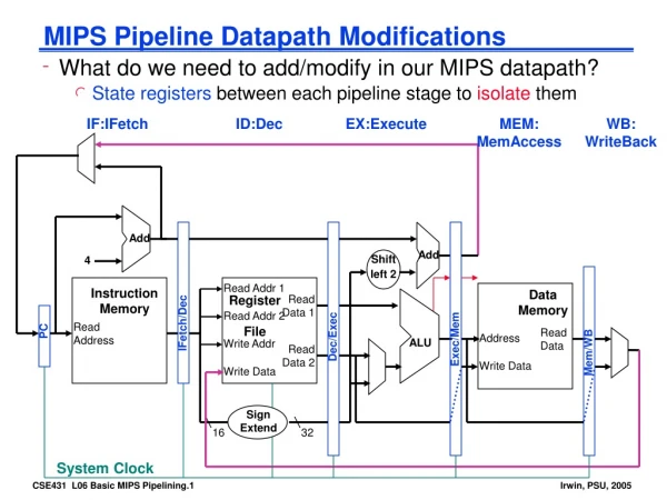
Instruction fetch Instruction Decode / register fetch Execute / address calculation Memory access Write back 0 PCSrc m u x 1 MEM/WB EX/MEM IF/ID ID/EX Add Add result 4 PC Branch Add RegWrite Shift left 2 Read reg 1 MemWrite Instruction Read data 1 Address Read reg 2 ALUSrc MemtoReg Register File Zero Read data 2 Instruction Read Data 0 Write reg 1 result Address ALU m u x m u x Instruction Memory Write data 1 Data Memory 0 Write Data 6 16 Sign extend 32 ALU Control [15-0] MemRead [20-16] 0 ALUOp m u x [15-11] 1 RegDst Pipelined CPU
Instruction Decode / register fetch Execute / address calculation Instruction fetch Memory access Write back ID/EX EX/MEM WB Control 0 MEM/WB WB PCSrc MEM m u x 1 WB MEM EXE IF/ID Add Add result 4 Branch PC Add RegWrite Shift left 2 Read reg 1 MemWrite Instruction Read data 1 Address Read reg 2 ALUSrc MemtoReg Register File Zero Read data 2 Instruction Read Data 0 Write reg 0 result Address ALU m u x m u x Instruction Memory Write data 1 Data Memory 1 Write Data 6 16 Sign extend 32 ALU Control [15-0] MemRead [20-16] ALUOp 0 m u x [15-11] 1 RegDst PipelinedCPU with Control
R e g I M R e g D M I M D M R e g R e g I M D M R e g R e g I M D M R e g R e g I M D M R e g R e g Structural Hazard • Attempt to use the same resource two different ways at the same time • Register File: • Accessed in 2 stages: • Read during stage 2 (ID) • Write during stage 5 (WB) • Solution: 2 read ports, 1 write port • Memory • Accessed in 2 stages: • Instruction Fetch during stage 1 (IF) • Data read/write during stage 4 (MEM) • Solution: separate instruction cache and data cache • Each functional unit can only be used once per instruction • Each functional unit must be used at the same stage for all instructions
0 PCSrc m u x 1 MEM/WB EX/MEM IF/ID ID/EX 4 Add Add result 4 Branch Add RegWrite Shift left 2 Read reg 1 MemWrite Instruction Read data 1 Address Read reg 2 ALUSrc MemtoReg Register File Zero lw Read data 2 Instruction Read Data PC 0 Write reg 1 result Address ALU m u x m u x Instruction Memory 4 Write data 1 Data Memory 0 Write Data 6 16 Sign extend 32 ALU Control [15-0] MemRead [20-16] 0 ALUOp m u x [15-11] 1 RegDst Pipeline Example: cycle 1 0 lw R10,9(R1) 4 sub R11,R2,R3 8 and R12,R4,R512 or R13,R6,R7
0 PCSrc m u x 1 MEM/WB EX/MEM IF/ID ID/EX 4 8 Add Add result 4 lw Branch Add RegWrite Shift left 2 Read reg 1 MemWrite Instruction [R1] Read data 1 Address Read reg 2 ALUSrc MemtoReg sub Register File Zero Read data 2 Instruction Read Data PC 0 Write reg 1 result Address ALU m u x m u x Instruction Memory 8 Write data 1 Data Memory 0 Write Data 6 16 Sign extend 32 ALU Control [15-0] 9 MemRead [20-16] 10 0 ALUOp m u x [15-11] 1 RegDst Pipeline Example: cycle 2 0 lw R10,9(R1) 4 sub R11,R2,R3 8 and R12,R4,R512 or R13,R6,R7
0 PCSrc m u x 1 MEM/WB EX/MEM IF/ID ID/EX 4 8 12 Add Add result 4 sub lw Branch Add RegWrite Shift left 2 Read reg 1 MemWrite Instruction [R2] Read data 1 Address Read reg 2 ALUSrc MemtoReg and Register File Zero PC [R3] Read data 2 Instruction Read Data [R1]+9 0 Write reg 1 result Address 12 ALU m u x m u x Instruction Memory Write data 1 Data Memory 0 Write Data 6 16 Sign extend 32 ALU Control [15-0] MemRead [20-16] 0 ALUOp m u x 10 [15-11] 11 1 RegDst Pipeline Example: cycle 3 0 lw R10,9(R1) 4 sub R11,R2,R3 8 and R12,R4,R512 or R13,R6,R7
Pipeline Example: cycle 4 0 PCSrc m u x 1 MEM/WB EX/MEM IF/ID ID/EX 4 8 16 12 Add Add result 4 and sub lw Branch Add RegWrite Shift left 2 Read reg 1 MemWrite Instruction [R4] Read data 1 Address Read reg 2 ALUSrc MemtoReg or Register File Zero PC [R5] Read data 2 Instruction Read Data [R2]-[R3] 0 Write reg 1 result Address 16 ALU m u x m u x Instruction Memory Data from memory address [R1]+9 Write data 1 Data Memory 0 Write Data 6 16 Sign extend 32 ALU Control [15-0] MemRead [20-16] 0 ALUOp m u x 11 10 [15-11] 12 1 RegDst 0 lw R10,9(R1) 4 sub R11,R2,R3 8 and R12,R4,R512 or R13,R6,R7
Time (clock cycles) C C 1 C C 2 C C 3 C C 4 C C 5 C C 6 C C 7 C C 8 C C 9 Program execution order 10 1 0 / – 2 0 Value of R2 10 10 10 -20 -20 -20 -20 R e g I M R e g D M I M D M R e g R e g I M D M R e g R e g I M D M R e g R e g I M D M R e g R e g Dependencies: RAW Hazard • Problem with starting next instruction before first is finished • dependencies that “go backward in time” are data hazards sub R2, R1, R3 and R12,R2, R5 or R13,R6, R2 add R14,R2, R2 sw R15,100(R2)
I I I M M M bubble bubble bubble bubble bubble bubble bubble bubble bubble bubble bubble bubble I M D M R e g R e g I M D M R e g R e g I M D M R e g R e g I M D M R e g R e g RAW Hazard: HW Solution 1 - Add Stalls • Have the hardware detect hazard and add stalls if needed Time (clock cycles) C C 1 C C 2 C C 3 C C 4 C C 5 C C 6 C C 7 C C 8 C C 9 Program execution order 10 1 0 / – 2 0 Value of R2 10 10 10 -20 -20 -20 -20 sub R2, R1, R3 stall stall stall and R12,R2, R5 or R13,R6, R2 add R14,R2, R2 sw R15,100(R2) R e g I M R e g D M • Problem: this also slows us down!
X X X X – 20 X X X X RAW Hazard: HW Solution 2 - Forwarding • Use temporary results, don’t wait for them to be written to the register file • register file forwarding to handle read/write to same register • ALU forwarding Time (clock cycles) C C 1 C C 2 C C 3 C C 4 C C 5 C C 6 C C 7 C C 8 C C 9 10 1 0 / – 2 0 Value of R2 10 10 10 -20 -20 -20 -20 Value EX/MEM X X X – 20 X X X X X Program execution order Value MEM/WB sub R2, R1, R3 and R12,R2, R5 or R13,R6, R2 add R14,R2, R2 sw R15,100(R2) I M R e g D M R e g I M R e g D M R e g I M R e g D M R e g I M R e g D M R e g I M R e g D M R e g
IF/ID MEM/WB ID/EX EX/MEM WB Control M WB M EX WB EX/MEM.RegWrite 0 m u x A MEM/WB.RegWrite 1 Instruction Register File 2 Instruction Memory Data Memory ALU PC 1 m u x 0 m u x B 0 1 2 IF/ID.Rs Rs IF/ID.Rt Rt IF/ID.Rt 0 Rt EX/MEM.Rd m u x IF/ID.Rd Rd 1 Forwarding Unit MEM/WB.Rd Forwarding Hardware
Forwarding Control • EX Hazard: • if (EX/MEM.RegWrite and (EX/MEM.WriteReg = ID/EX.ReadReg1)) ALUSelA = 1 • if (EX/MEM.RegWrite and (EX/MEM.WriteReg = ID/EX.ReadReg2)) ALUSelB = 1 • MEM Hazard: • if (MEM/WB.RegWrite and ((not EX/MEM.RegWrite) or (EX/MEM.WriteReg ID/EX.ReadReg1)) and (MEM/WB.WriteReg = ID/EX.ReadReg1)) ALUSelA = 2 • if (MEM/WB.RegWrite and ((not EX/MEM.RegWrite) or (EX/MEM.WriteReg ID/EX.ReadReg2)) and (MEM/WB.WriteReg = ID/EX.ReadReg2)) ALUSelB = 2
IF/ID MEM/WB ID/EX EX/MEM WB Control M WB M EX WB [R10] 0 sub lw m u x 1 Instruction and Register File 2 Instruction Memory Data Memory [R2]-[R3] ALU PC 1 Data from memory address [R1]+9 m u x [R11] 0 m u x 0 1 2 IF/ID.Rs Rs 10 IF/ID.Rt Rt 11 IF/ID.Rt 0 Rt EX/MEM.Rd m u x 10 11 IF/ID.Rd Rd 12 1 Forwarding Unit MEM/WB.Rd Forwarding Hardware Example: Bypassing From EX to Src1 and From WB to Src2 lw R11,9(R1) sub R10,R2, R3and R12,R10,R11
IF/ID MEM/WB ID/EX EX/MEM WB Control M WB M EX WB [R11] 0 xxx sub m u x 1 Instruction and Register File 2 Instruction Memory Data Memory ALU PC 1 [R2]-[R3] m u x [R10] 0 m u x 0 1 2 IF/ID.Rs Rs 10 IF/ID.Rt Rt 11 IF/ID.Rt 0 Rt EX/MEM.Rd m u x 10 IF/ID.Rd Rd 12 1 Forwarding Unit MEM/WB.Rd Forwarding Hardware Example 2: Bypassing From WB to Src2 sub R10,R2, R3 xxxand R12,R10,R11
R R R e e e g g g Register File Split • Register file is written during first half of the cycle • Register file is read during second half of the cycle • Register file is written before it is read returns the correct data sub R2, R1, R3 xxx xxx and R12,R2,R11 R e g I M R e g D M I M D M I M D M R e g I M D M R e g R e g
Program execution order Can't always forward • Load word can still causes a hazard: • an instruction tries to read a register following a load instruction that writes to the same register Time (clock cycles) C C 1 C C 2 C C 3 C C 4 C C 5 C C 6 C C 7 C C 8 C C 9 lw R2, 30(R1) and R12,R2, R5 or R13,R6, R2 add R14,R2, R2 sw R15,100(R2) R e g I M D M R e g I M R e g D M R e g I M R e g D M R e g I M R e g D M R e g I M D M R e g R e g • A hazard detection unit is needed to “stall” the load instruction
Program execution order Time (clock cycles) C C 1 C C 2 C C 3 C C 4 C C 5 C C 6 C C 7 C C 8 C C 9 lw R2, 30(R1) and R12,R2, R5 or R13,R6, R2 add R14,R2, R2 sw R15,100(R2) R e g D M R e g I M R e g D M I M R e g R e g R e g D M R e g I M I M b u b b l e R e g I M D M R e g R e g D M I M R e g Stalling • De-assert the enable to ID/EXE • The dependant instruction (and) stays another cycle in IF/EXE • De-assert the enable to the IF/ID latch, and to the PC • Freeze pipeline stages preceding the stalled instruction • Issue a NOP into the EXE/MEM latch (instead of the stalled inst.) • Allow the stalling instruction (lw) to move on
Hazard Detection (Stall) Logic if (ID/EX.RegWrite and (ID/EX.opcode = lw) and ( (ID/EX.WriteReg = IF/ID.ReadReg1) or (ID/EX.WriteReg = IF/ID.ReadReg2) ) then stall
ID/EX.MemRead Hazard Detection Unit IF/ID MEM/WB ID/EX EX/MEM WB IF/ID Write Control M WB 0 PC Write m u x M EX WB 0 1 0 m u x 1 Instruction Register File 2 Instruction Memory Data Memory ALU PC 1 m u x 0 m u x 0 1 2 IF/ID.Rs Rs IF/ID.Rt Rt IF/ID.Rt 0 Rt EX/MEM.Rd m u x IF/ID.Rd Rd 1 Forwarding Unit MEM/WB.Rd ID/EX.Rt Forwarding + Hazard Detection Unit
Software Scheduling to Avoid Load Hazards Example: code for (assume all variables are in memory): a = b + c; d = e – f; Slow code LW Rb,b LW Rc,c Stall ADD Ra,Rb,Rc SW a,Ra LW Re,e LW Rf,f Stall SUB Rd,Re,Rf SW d,Rd Instruction order can be changed as long as the correctness is kept Fast code LW Rb,b LW Rc,c LW Re,e ADD Ra,Rb,Rc LW Rf,f SW a,Ra SUB Rd,Re,Rf SW d,Rd
0 PCSrc Calculate branch target m u x 1 MEM/WB EX/MEM IF/ID ID/EX 8 12 Add Add result 4 and beq Branch Add RegWrite Shift left 2 Read reg 1 MemWrite Instruction R4 - PC Read data 1 Address Read reg 2 ALUSrc 12 MemtoReg Register File Zero R5 Read data 2 Instruction Read Data Write reg 0 0 result Address ALU m u x m u x Instruction Memory Write data 1 Data Memory 1 Write Data 6 16 Sign extend 32 ALU Control [15-0] 27 MemRead [20-16] 0 ALUOp m u x [15-11] 1 RegDst Executing a BEQ Instruction (i) BEQ R4, R5, 27 ; if (R4-R5=0) then PC PC+4+SignExt(27)*4 ; else PC PC+4 0 or 4 beq R4, R5, 27 8 and12 sw 16 sub Calculate branch condition
0 8+SignExt(27)*4 PCSrc m u x 1 MEM/WB EX/MEM IF/ID ID/EX 16 12 Add Add result 4 Branch Add RegWrite Shift left 2 beq sw and Read reg 1 MemWrite Instruction - Read data 1 Address PC Read reg 2 R4-R5=0 ALUSrc MemtoReg Register File Zero 16 Read data 2 Instruction Read Data 0 Write reg 0 result Address ALU m u x m u x Instruction Memory Write data 1 Data Memory 1 Write Data 6 16 Sign extend 32 ALU Control [15-0] MemRead [20-16] 0 ALUOp m u x [15-11] 1 RegDst Executing a BEQ Instruction (ii) BEQ R4, R5, 27 ; if (R4-R5=0) then PC PC+4+SignExt(27)*4 ; else PC PC+4 0 or 4 beq R4, R5, 27 8 and12 sw 16 sub
0 8+SignExt(27)*4 PCSrc m u x 1 MEM/WB EX/MEM IF/ID ID/EX 16 Add 20 Add result 4 Branch Add RegWrite Shift left 2 beq sub sw and Read reg 1 MemWrite Instruction Read data 1 Address PC Read reg 2 ALUSrc MemtoReg Register File Zero 20 or 116 Read data 2 Instruction Read Data 0 Write reg 0 result Address ALU m u x m u x Instruction Memory Write data 1 Data Memory 1 Write Data 6 16 Sign extend 32 ALU Control [15-0] MemRead [20-16] 0 ALUOp m u x [15-11] 1 RegDst Executing a BEQ Instruction (iii) BEQ R4, R5, 27 ; if (R4-R5=0) then PC PC+4+SignExt(27)*4 ; else PC PC+4 0 or 4 beq R4, R5, 27 8 and12 sw 16 sub
PC R R R e e e g g g I I I M M M R R R e e e g g g D D D M M M R e g I M R e g D M PC PC PC PC R e g I M R e g D M Control Hazard on Branches Beq And The 3 instructions following the branch get into the pipe even if the branch is taken sw sub Inst from target
Control Hazard: Stall • Stall pipe when branch is encountered until resolved • Stall impact: assumptions • CPI = 1 • 20% of instructions are branches • Stall 3 cycles on every branch CPI new = 1 + 0.2 × 3 = 1.6 (CPI new = CPI Ideal + avg. stall cycles / instr.) We loose 60% of the performance
Control Hazard: Predict Not Taken • Execute instructions from the fall-through (not-taken) path • As if there is no branch • If the branch is not-taken (~50%), no penalty is paid • If branch actually taken • Flush the fall-through path instructions before they change the machine state (memory / registers) • Fetch the instructions from the correct (taken) path • Assuming ~50% branches not taken on average CPI new = 1 + (0.2 × 0.5) × 3 = 1.3
PC of inst in fetch Look up Branch PC Target PC History Predicted Target Branch predicted taken or not taken ?= Yes:Inst is pred to be branch No:Inst is not pred to be branch Dynamic Branch Prediction • Add a Branch Target Buffer (BTB) the predicts (at fetch) • Instruction is a branch • Branch taken / not-taken • Taken branch target
BTB • Allocation • Allocate instructions identified as branches (after decode) • Both conditional and unconditional branches are allocated • Not taken branches need not be allocated • BTB miss implicitly predicts not-taken • Prediction • BTB lookup is done parallel to IC lookup • BTB provides • Indication that the instruction is a branch (BTB hits) • Branch predicted target • Branch predicted direction • Branch predicted type (e.g., conditional, unconditional) • Update (when branch outcome is known) • Branch target • Branch history (taken / not-taken)
BTB (cont.) • Wrong prediction • Predict not-taken, actual taken • Predict taken, actual not-taken, or actual taken but wrong target • In case of wrong prediction – flush the pipeline • Reset latches (same as making all instructions to be NOPs) • Select the PC source to be from the correct path • Need get the fall-through with the branch • Start fetching instruction from correct path • Assuming P% correct prediction rate CPI new = 1 + (0.2 × (1-P)) × 3 • For example, if P=0.7 CPI new = 1 + (0.2 × 0.3) × 3 = 1.18
Flush taken target 0 PCSrc PC+4 (Not-taken target) MEM /WB m u x 1 EX/MEM 2 3 IF/ID ID/EX Mis- predict Detection Unit predicted direction predicted target PC+4 (Not-taken target) + 4 + RegWrite Shift left 2 Branch PC BTB Read reg 1 MemWrite Instruction pred target Read data 1 Read reg 2 ALUSrc pred dir MemtoReg Register File Zero direction Read data 2 Read Data 0 Write reg 1 result Address target ALU m u x alloc/updt m u x Write data − 1 Data Memory address 0 Write Data 4 6 16 Sign extend 32 ALU Control Address [15-0] MemRead Instruction [20-16] 0 Inst. Memory ALUOp m u x [15-11] 1 RegDst Adding a BTB to the Pipeline
BTB Hit ? Br taken ? Branch ? Using The BTB PC moves to next instruction Inst Mem gets PC and fetches new inst BTB gets PC and looks it up IF yes no yes no IF/ID latch loaded with new inst PC perd addr PC PC + 4 ID IF/ID latch loaded with pred inst IF/ID latch loaded with seq. inst EXE yes no
Branch ? Corect pred ? Using The BTB (cont.) ID no yes EXE Calculate br cond & trgt continue Update BTB yes no MEM continue Flush pipe & update PC WB IF/ID latch loaded with correct inst
16 11 6 0 31 26 21 rt rd shamt funct op rs 5 bits 5 bits 5 bits 6 bits 6 bits 5 bits 16 0 31 26 21 immediate rt op rs 5 bits 16 bits 6 bits 5 bits 0 31 26 target address op 26 bits 6 bits MIPS Instruction Formats • R-type • (register insts) • I-type (Load, • Store, Branch, • inst’s w/imm • data) • J-type (Jump) • op: operation of the instruction • rs, rt, rd: the source and destination register specifiers • shamt: shift amount • funct: selects the variant of the operation in the “op” field • address / immediate: address offset or immediate value • target address: target address of the jump instruction
1 byte 00000000 00000001 00000002 00000003 00000004 00000005 00000006 FFFFFFFA FFFFFFFB FFFFFFFC FFFFFFFD FFFFFFFE FFFFFFFF The Memory Space • Each memory location • is 8 bit = 1 byte wide • has an address • We assume 32 byte address • An address space of 232 bytes • Memory stores both instructions and data • Each instruction is 32 bit wide stored in 4 consecutive bytes in memory • Various data types have different width
RegWrite 5 Read reg 1 32 Read data 1 5 Read reg 2 Register File 5 32 Write reg Read data2 32 Write data Register File • The Register File holds 32 registers • Each register is 32 bit wide • The RF supports parallel • reading any two registers and • writing any register • Inputs • Read reg 1/2: #register whose value will be output on Read data 1/2 • RegWrite: write enable • Write reg (relevant when RegWrite=1) • #register to which the value in Write data is written to • Write data (relevant when RegWrite=1) • data written to Write reg • Outputs • Read data 1/2: data read from Read reg 1/2
Write 32 Address 32 Read Data Memory 32 Write Data Read Memory Components • Inputs • Address: address of the memory location we wish to access • Read: read data from location • Write: write data into location • Write data (relevant when Write=1) data to be written into specified location • Outputs • Read data (relevant when Read=1) data read from specified location Cache • Memory components are slow relative to the CPU • A cache is a fast memory which contains only small part of the memory • Instruction cache stores parts of the memory space which hold code • Data Cache stores parts of the memory space which hold data
The Program Counter (PC) • Holds the address (in memory) of the next instruction to be executed • After each instruction, advanced to point to the next instruction • If the current instruction is not a taken branch, the next instruction resides right after the current instruction PC PC + 4 • If the current instruction is a taken branch, the next instruction resides at the branch target PC target (absolute jump) PC PC + 4 + offset×4 (relative jump)
Instruction Execution Stages • Fetch • Fetch instruction pointed by PC from I-Cache • Decode • Decode instruction (generate control signals) • Fetch operands from register file • Execute • For a memory access: calculate effective address • For an ALU operation: execute operation in ALU • For a branch: calculate condition and target • Memory Access • For load: read data from memory • For store: write data into memory • Write Back • Write result back to register file • update program counter Instruction Fetch Instruction Decode Execute Memory Result Store
Shift left 2 Add 4 Add Control PCSrc 0 m u x RegWrite 0 1 m u x [25-21] Read reg 1 Read data 1 MemWrite Branch 1 ALU PC [20-16] MemtoReg Address Read reg 2 ALUSrc Zero Sign extend Register File Instruction ALU res Address Instruction Write reg Read Data Read data 2 [15-11] Instruction Cache Write data RegDst Data Cache Write Data 1 0 16 m u x m u x 32 [15-0] ALU Control MemRead 0 1 [5-0] ALUOp The MIPS CPU Instruction fetch Instruction Decode / register fetch Execute / address calculation Memory access Write back
op rs rt rd shamt funct 31 26 21 16 11 6 0 ALU 3 5 2 0 0 = Add Shift left 2 Add 4 Add 0 m u x PCSrc=0 0 RegWrite=1 1 m u x 1 [25-21] Read reg 1 MemWrite=0 Read data 1 Branch=0 ALU PC Sign extend [20-16] MemtoReg=0 ALUSrc=0 Address Read reg 2 Zero Register File Instruction ALU res Address Instruction Write reg Read Data Read data 2 [15-11] Instruction Memory Write data RegDst=1 Data Memory 1 0 Write Data m u x m u x 16 32 [15-0] 0 1 ALU Control MemRead=0 [5-0] ALUOp Executing an Add Instruction Add R2, R3, R5 ; R2 R3+R5 [PC]+4 R3 3 5 ADD + 2 R5 R3 + R5
op rs rt immediate 31 26 21 16 0 LW 2 1 30 Shift left 2 [PC]+4 Add 4 Add 0 m u x PCSrc=0 0 RegWrite=1 1 m u x R2 2 1 [25-21] Read reg 1 Read data 1 MemWrite=0 Branch=0 ALU PC LW + Sign extend [20-16] R2+30 ALUSrc=1 MemtoReg=1 Address Read reg 2 Zero Register File 1 Instruction ALU res Address Instruction Write reg Read Data Read data 2 [15-11] Instruction Memory Write data RegDst=0 Data Memory 1 0 Write Data m u x m u x 30 16 32 [15-0] 0 1 ALU Control MemRead=1 [5-0] Mem[R2+30] ALUOp Executing a Load Instruction LW R1, (30)R2 ; R1 Mem[R2+30]
op rs rt immediate 31 26 21 16 0 SW 2 1 30 Shift left 2 [PC]+4 Add 4 Add 0 m u x PCSrc = 0 0 RegWrite =0 1 m u x R2 2 1 [25-21] Read reg 1 Read data 1 MemWrite = 1 Branch=0 1 ALU PC SW + Sign extend [20-16] R2+30 MemtoReg = ALUSrc = 1 Address Read reg 2 Zero Register File Instruction ALU res Address Instruction Write reg Read Data Read data 2 [15-11] R1 Instruction Memory Write data RegDst = Data Memory 1 0 Write Data m u x m u x 30 16 32 [15-0] 0 1 ALU Control MemRead [5-0] ALUOp Executing a Store Instruction SW R1, (30)R2 ; Mem[R2+30] R1
Shift left 2 PC+4 or PC+4+SignExt(27)*4 PC+4 Add 4 Add 0 m u x PCSrc=(R4 – R5 == 0) 0 RegWrite=0 1 m u x R4 4 1 [25-21] Read reg 1 MemWrite=0 Branch=1 Read data 1 - 5 ALU PC ADD MemtoReg= Sign extend [20-16] ALUSrc=0 Address Read reg 2 Zero R4-R5 Register File Instruction ALU res Address Instruction Write reg Read Data Read data 2 R5 [15-11] Instruction Memory Write data RegDst= Data Memory 0 1 Write Data m u x m u x 16 32 [15-0] 0 1 ALU Control MemRead=0 27 [5-0] ALUOp Executing a BEQ Instruction BEQ R4, R5, 27 ; if (R4-R5=0) then PC PC+4+SignExt(27)*4 ; else PC PC+4 op rs rt immediate 31 26 21 16 0 BEQ 4 5 27
func 10 0000 10 0010 Don’t Care op 00 0000 00 0000 00 1101 10 0011 10 1011 00 0100 00 0010 add sub ori lw sw beq jump RegDst 1 1 0 0 x x x ALUSrc 0 0 1 1 1 0 x MemtoReg 0 0 0 1 x x x RegWrite 1 1 1 1 0 0 0 MemWrite 0 0 0 0 1 0 0 Branch 0 0 0 0 0 1 x Jump 0 0 0 0 0 0 1 ALUctr<2:0> Add Subtract Or Add Add xxx Subtract Control Signals