Download
1 / 22
220 likes | 459 Views
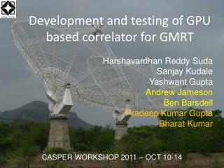
Development and testing of GPU based correlator for GMRT. Harshavardhan Reddy Suda Sanjay Kudale Yashwant Gupta Andrew Jameson Ben Barsdell Pradeep Kumar Gupta Bharat Kumar. CASPER WORKSHOP 2011 – OCT 10-14. Introduction. Correlator developed with both FPGA and GPU

E N D
Development and testing of GPU based correlator for GMRT Harshavardhan Reddy Suda Sanjay Kudale Yashwant Gupta Andrew Jameson Ben Barsdell Pradeep Kumar Gupta Bharat Kumar CASPER WORKSHOP 2011 – OCT 10-14
Introduction • Correlator developed with both FPGA and GPU • FPGA board along with ADC for sampling the input signal and packetising • CPU-GPU to perform the correlation process • Hardware : ROACH/IBOB board with iADC Dell T7500 machine with C1060/C2050 nvidia GPU card and Myricom 10GbE NIC • Software : PSRDADA and GMRT GPU correlator developed in collaboration with Swinburne University, Australia
Data Flow FPGA (ROACH/IBOB) Antenna1 10GbE link Sampling FIFO 1 Mux Packetising Clock Antenna2 FIFO 2 Control Logic Shared Memory1 Integer delay Antenna1 Unpacking(Demux) 10 GbE NIC Shared Memory2 Integer delay Antenna2 Data Transfer to GPU Floating point conversion FFT Fractional delay and Fringe Antenna1 Multiplication and Accumulation Floating point conversion FFT Fractional delay and Fringe Antenna2 Data visualization program Writing results back to CPU CPU-GPU
About Software • PSRDADA: • Acronym for Parkes Swinburne Recorder Distributed Acquisition and Data Analysis • Modified it for GMRT in collaboration with Swinburne University • Language: C Functions it does: • Creates the shared memories • Receives the data from the 10GbE link • Performs integer delay correction from the values provided by Delay cal software • Writes the data to shared memories
GMRT GPU Correlator : • Developed in collaboration with Swinburne University • Generalized application for upto 32 antennas • Language : C for CUDA • Provision for profiling and offline testing • Code has been optimised (FFT and Streaming) with help from nVIDIA. Functions it does: • Reads the shared memories and copies the data into GPU • Floating point conversion. Provision for both 8-bit and 4-bit data • Fast Fourier Transform using CUFFT library • Fractional delay and Fringe compensation • Multiplication and Accumulation • Writes the results back to CPU
2 antenna GPU correlator specs Sampling Frequency : 400MHZ,8-bits per sample FFT size : 2048 Integration time : 0.671088 s(256MB of data at 400MHZ Sampling) Delay and fringe compensations
Test results: Self spectrum of two GMRT antennas from frequencies 1.4 to 1.2 GHZ on source 3C286 S02 Power(Arb. Unit) C06 Power(Arb. Unit) Channel No.
Visibility amplitude and Phase for two GMRT antennas - integration of 0.671s – source 3C286 Cross Phase Phase in deg. Normalized Cross Amp Channel No.
Phase Stability: A single frequency channel’s cross amplitude and phase plotted over time for nearly three hours Phase Phase in deg. Normalized Cross Amp
Cross Phase comparision with the existing correlator at GMRTData collected for ~3 hours on 3C286 GPU Phase in deg. GSB Phase in deg.
Performance of GPU: • Tests conducted with raw data collected from noise source at sampling of 400MHZ. Each data file of 400MB which is 1 sec of data for both iADC inputs. • Timing results: For 2-antennas and integration time of 1 sec File reading : 239 ms Host to device transfer : 162 ms(Bandwidth comes out to 4.93GB/S) Floating Point conversion : 83 ms Fast Fourier Transform : 152 ms Phase Shifting(Fractional delay and fringe correction) : 66 ms MAC : 115 ms Total time for processing : 0.405536 s Total BW that can be processed = 517.131 MHZ
Plots to check the integrity of the test Self 2 Self 1 Phase Normalized Cross
For 32-antennas and integration time of 1 sec The two raw data files duplicated 16 times for having 32 data files File reading : 2748 ms Host to Device Transfer : 2557 ms(Bandwidth comes out to 5.00GB/S) Floating point conversion : 889 ms Fast Fourier Transform : 2201 ms Phase Shifting(Fractional delay and fringe correction) : 101 ms MAC : 8441 ms Total time for processing : 12.5833 s Total BW that can be processed = 16.6662 MHZ
Processable BW in MHZ for Unoptimised and Optimised code on Tesla C1060 Antennas
Processable BW in MHZ for Unoptimised and Optimised code on Tesla C2050 Antennas
What is the significance of processable BW?? • GMRT being upgraded from 32 MHZ processing BW to 400 MHZ • Number of GPUs needed for the upgrade 400/16.6662 = • IO requirements: Data from each antenna : 800 MillionBytes Per Machine : 800 * 32 / 25 = 1024 MillionBytes Sustainable by 10GbE network • For sending data from 32 10GbE links to 25 machines, time slicing is needed. • Can time slicing be done on ROACH/IBOB boards? • So, estimated one Machine per antenna, total 32 Machines 25 (rounded to upper integer)
Future Plan • To build a cluster for 32-antennas of GMRT using MPI , CUDA and OpenMP in collaboration with nVIDIA • Two Plans proposed • Plan 1 : With 32 CPU-GPU machines each with 10GbE card, Infiniband interface and a GPU • Plan 2 : With 25 CPU-GPU machines each with 10GbE card and GPU Further Data Acquisition and Distribution Machines are needed for sending time sliced data
Proposed Plan 1 : For single polarisation ROACH/ IBOB 1 ROACH/ IBOB 2 ROACH/ IBOB 16 800MiB/S 800MiB/S 800MiB/S 800MiB/S 800MiB/S 800MiB/S CPU-GPU 1 CPU-GPU 2 CPU-GPU 3 CPU-GPU 4 CPU-GPU 31 CPU-GPU 32 INFINIBAND SWITCH (20/40 GbPS)
Proposed Plan 2 : For single polarisation ROACH/ IBOB 1 ROACH/ IBOB 2 ROACH/ IBOB 16 800MiB/S 800MiB/S 800MiB/S 800MiB/S 800MiB/S 800MiB/S ACQPC1 ACQPC 2 ACQPC 3 ACQPC4 ACQ PC 31 ACQPC 32 Time sliced data INFINIBAND SWITCH (20/40 GbPS) CPU-GPU 1 CPU-GPU 2 CPU-GPU 3 CPU-GPU 4 CPU-GPU 24 CPU-GPU 25
AcknowledgementDigital Backend Group, GMRT Yashwant Gupta Ajith Kumar B Sanjay Kudale Sandeep Chaudhari Shelton Gnanaraj Mekhala Muley Kaushal Buch Irappa Halagali Mangesh Umbarje