Download
1 / 66
660 likes | 820 Views
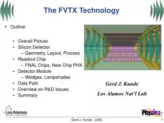
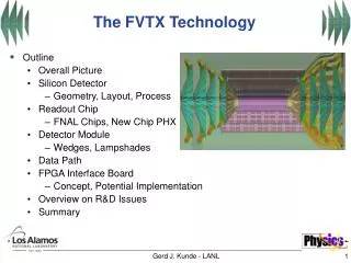
The FVTX Technology. Outline Overall Picture Silicon Detector Geometry, Layout, Process Readout Chip FNAL Chips, New Chip PHX Detector Module Wedges, Lampshades Data Path FPGA Interface Board Concept, Potential Implementation Overview on R&D Issues Summary.

E N D
The FVTX Technology • Outline • Overall Picture • Silicon Detector • Geometry, Layout, Process • Readout Chip • FNAL Chips, New Chip PHX • Detector Module • Wedges, Lampshades • Data Path • FPGA Interface Board • Concept, Potential Implementation • Overview on R&D Issues • Summary Gerd J. Kunde - LANL
FVTX Tracker Executive Summary • Four lampshade stations on each side • Mini-strips of 50 micron radial pitch: 2.2 -13 mm • Readout via new PHX chip from Fermi Nat’l Lab • Total strip count: ~ 2 * 860,000 strips (zero suppressed) • Total chip count: ~ 2 * 1680 chips • Total silicon area: ~ 2 *3350 cm2 Gerd J. Kunde - LANL
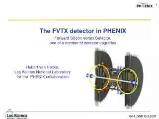
The Inner Volume of Phenix 78 cm 66 cm 45 cm Mechanical Design for VTX and FVTX by LANL & Hytec Gerd J. Kunde - LANL
Endcap (north and south) z-start(+-) o-radius tilt = 22 deg station 1 20 cm 6.6 cm ministrip station 2 26 cm 10.6cm ministrip station 3 32 cm 18 cm ministrip station 4 38 cm 18 cm ministrip Current VTX & FVTX Specifications 1.2% 2.0% Rad. Length 1 % Gerd J. Kunde - LANL
FVTX Part of VERTEX Spreadsheet Gerd J. Kunde - LANL
2816 2048 1280 Silicon Detector Technical Overview • 200 micron thickness • 50 micron radial pitch (z reconstruction) • curved or straight strips ? (R&D) • 1280,2048,2816 “mini-strips” • 3.5 cm < r < 18 cm • < 1.5 % occupancy (central AA) • 48 “double towers” in phi • mini-strips from 13.0 mm to 2.2 mm • readout via PHX 5,8,11 chip row r = 18.0 cm r = 3.5 cm 1 PHX derived from FNAL chips Gerd J. Kunde - LANL
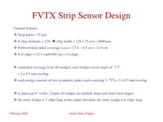
Only “2 ½” Silicon Detector types 50 micron strips (collaboration with Prague groups) Outside Detector (II) Outside Detector (III) Inside Detector (I) 5 chips= 1280 * 2 strips 706.2 mm^2 6 chips= 1536 * 2 strips 1698.5 mm^2 3 chips= 768 * 2 strips 752.0 mm^2 Gerd J. Kunde - LANL
Two Silicon Wafer Layout Concepts n+ pixels on n substrate using “moderated p-spray” as the n-isolation technology Proven ATLAS/BTev technology with existing qualified vendors We assume 4 inch - 200 um wafers, the layout is matching the need of inner and outer detectors: Inner: 77 wafers + contingency Outer: 96 wafers + contingency Gerd J. Kunde - LANL
Silicon Sensor Schedule Gerd J. Kunde - LANL
Existing FNAL Chip: FPIX2.1 Features • Advanced mixed analog/digital design • 128 rows x 22 columns (2816 channels) • 50 µm x 400 µm pixels • High speed readout intended for use in Level 1 trigger. Up to 840 Mbits/sec data output. • Very low noise, excellent threshold matching • DC coupled input • Fully programmable device • Output directly drives long cable (10 m, 30 feet) • 90 mirco watt/pixel • (~0.25 watt/chip) • Rad hard to 50 Mrads Change geometry for PHX-chip and adjust analog front end to mini-strips capacity Gerd J. Kunde - LANL
3 bit ADC PHX Simulation PHX Simulation Signal/Noise ~ 50/1 Threshold/Noise ~ 10/1 for mini-strips on 200 um Si 2 mm to 10 mm strip length FPIX 2.1 Pixel Circuit (50 x 400 µm) FPIX2: 60 e-rms measured noise @ c=0 pf Gerd J. Kunde - LANL
FPIX 2 Module: “Real” Threshold and Noise CHIP 4 CHIP 4 These are typical distribution curves for threshold and noise for a real chip on an 8 chip HDI. (A mip gives 16,000 electrons in 200 micron) Gerd J. Kunde - LANL
Measured FPIX 2 Power Consumption The power consumption of the 8 chip module is: for (VD=VA=2.5V) 1.86W Module idle. 2.26W Module collecting data.* 100 micro watt/channel for (VD=VA=2.2V) 1.51W Module idle. 1.83W Module collecting data.* 80 micro watt/channel * 8 chip module collecting data at 300Mbps. The power consumption variation due temperature change (delta=100ºC) was less than 0.05 W. Gerd J. Kunde - LANL
signals & power Bump bonds Programming interface Discriminator Pipeline Digital interface signals & power FNAL Collaboration Ray Yarema’s group PHX Chip Layout: 2 columns 256 channels/column 3.8 mm x 13 mm = 49.4 mm2 Thinned to 150 to 200 um Bump bonds on 200 um pitch 50 µm dia solder bumps 512 bumps plus inter-chip bumps ~ 15 wafers needed Keep all digital backend the same ! Adjust only input and geometry, optimize the row/column structure for readout speed and add pulser. Bus on chip ? Gerd J. Kunde - LANL
Kapton Kapton R&D necessary …. fallback solution is Flex Cable with Wire Bonding PHX Bus R&D FNAL Proposal: Power & Data Bus on Chip PHX PHX 200 um Silicon Detector Preliminary calculations by R.Yarema show that the I-R loss is acceptable, need optimize number of signal lines per chip Gerd J. Kunde - LANL
FVTX Power Numbers added for both sides ! ~3400 chips but only 80 Watts per Endcap Gerd J. Kunde - LANL
PHX Chip Development Schedule Gerd J. Kunde - LANL
2 silicons in front 2 silicons in back Eliminate dead silicon areas by overlapping 1 mm along edges …. FVTX Wedge Assembly 3 mm carbon wedge for assembly and cooling Carbon Fiber Support and Cooling Gerd J. Kunde - LANL
From Wedges to Lampshades X 24 Total strip count: ~ 2 * 860,000 strips Total chip count: ~ 2 * 1680 chips Total silicon area: ~ 2 * 3350 cm2 Gerd J. Kunde - LANL
48 per station Fiber 4 Gbit/s Serializer Optical Driver Slow Control ~100 Hz 5 x 512 channels 5 x 512 channels FVTX Connections Copper Flex (Fiber) 48 per station Copper Cables 61 LVDS Pairs Copper Bus LVDS 4 x 169.8 MBit Hit: 9 bit address ,3 bit adc, 4 bit chip-id, tag 8bit => 24 bits 6 x 512 channels 5 x 512 channels • R&D Project: Flex Cables or Fiber to the ‘outside world’ ? • Space Constraints (see W.Sondheim) • Costs/Complexity/Reliability • Serializer/Fiber Collaboration ? Gerd J. Kunde - LANL
D.Christian Slide FVTX Copper Connection Wire Count • Per wedge: 6x2=12 wires • BCO clock • Shift In • Shift Out • Shift Control • Reset • MC • Per chip: • Data out (x1,2,4,6) • DLCLK • 11 chips/wedge… assume we use DLCLK: • 1 serial pair/chip: 6 pairs+11x2 pairs = 28 pairs • 2 serial pairs/chip: 6 pairs + 11x3 pairs = 39 pairs • 4 serial pairs/chip: 6 pairs + 11x5 pairs = 61 pairs • Power and Bias • ‘Round Cable’ ala CDF/D0 Gerd J. Kunde - LANL
Samtech QSS-RA100 .635mm pitch Connector (7mmx54mm) 24 Fiber MPO Connector (x8) 160 mm 30mm 12 fibers per connector FVTX Connections III Board(green) and fiber optic connector(orange) • R&D Project: Flex Cables or Fibers the ‘outside world’ ? • Space Constraints (see W.Sondheim) Gerd J. Kunde - LANL
Electronics Readout Concept Event Tag chip download Driver (buffer) FPGA PHENIX DCM Copper ~140 Mbits/s Data out <1.5 % Occupancy in AA central Level 1 possible fiber copper Level 1 Accept PHX/FPIX2 is zero suppressed !!! To Level 1 trigger processor T&FC Fvtx Interface Board Slow controls In Counting House In Detector Gerd J. Kunde - LANL
R&D on Data Acquisition (Number of Readout Lines, Clock Speed & FPGA Memory) R & D has started under LANL DR grant First FVTX readout meeting (Columbia/ISU/LANL) held 12/5/2005 at BNL Gerd J. Kunde - LANL
ISU Level 1 Board (SBIR) FVTX DAQ INTERFACE BOARD • Serial download to chips • Pass beam clock • Initialize/Reset Arcnet (FPGA program., chip download) T+FC On Silicon 11?, 41?/FPGA Trigger? Near Silicon Outside IR Conventional Copper Cable or Serializer/Optical Driver Data Buffer, FPGA Time to process=? DCM 2.5 Gb/s PHX • 1,2,4,(6) lines/chip • Stream of 24-bit data words with: • Location • (3 bit ADC) • Beam Clock Counter • 140Mbps readout lines can drive 10 m Uses custom or commercial driver • Buffers Data • Upon lvl1 grab relevant data • Build packet • DataDCM/Lvl1 • Pass beam clock • Initialize chips PHENIX Standard New development of FIB and firmware (Columbia/LANL) Gerd J. Kunde - LANL
The FIB Concept (FVTX Interface Board)(with input from Chi,FNAL + Columbia) Gerd J. Kunde - LANL
FVTX Research & Development • Silicon Detector • Adapt/modify existing design • Straight or curved strips • PHX Chip • Low risk modification of existing design • Analog input, row/column structure, pulser • New development • Bus on chip • Interfacing • Flex copper cables or Fibers • R&D • Transition Board • New development • FVTX Interface Board (FIB) and firmware • DAQ/Slow Control • Mechanics/Cooling integrated in VTX solution • See W. Sondheim’s presentation Gerd J. Kunde - LANL
FVTX Summary • North and South: 4 Station Precision Silicon Tracker for the Muon Arms • BTeV (ATLAS) Technology for Detector and Readout Chip • R&D Schedule (needs to start now) • FVTX (DAQ) Interface Board with FPGA and Firmware • R &D started under LANL grant • Collaboration with Columbia/ISU • Mechanics covered in next talk • Detailed Schedule in Dave’s talk Gerd J. Kunde - LANL
BACKUP Slides on the FVTX Gerd J. Kunde - LANL
FNAL Chip Comparison Signal 24000 e for 300 µm Si Sensor, thinning desirable for small material budget Gerd J. Kunde - LANL
R.Yarema Slide FPIX2.1 Pixel Cells 50 x 400 um 12 µm bump pads Preamp 2nd stage +disc Kill/ inject ADC encoder Digital interface ADC Gerd J. Kunde - LANL
R.Yarema Slide Power Considerations • Must minimize IR drops • Reduce number of chips on bus • Design full custom low power analog and digital sections • Maximize power bus size on chip • Use back side contact • Possibly use cooling structure for ground return Gerd J. Kunde - LANL
R.Yarema Slide Voltage Drop Estimation • Units are connected as shown • Each unit consumes current • What is the IR drop at the output of the last unit? n identical units Gerd J. Kunde - LANL
R.Yarema Slide Runit Estimation(one chip is a unit) Gerd J. Kunde - LANL
R.Yarema Slide Iunit Estimation • FPIX2 uses 60mA of Analog Current and 60mA of Digital Current. • It is fairly accurate to use the FPIX2 Analog Current as an estimation of the Phoenix Mini Strip Analog Current. • It is conservative to use the FPIX2 Digital Current as an estimation of the Phoenix Mini Strip Digital Current • Phenix Mini Strip will not read out at 840MBits/sec • Phenix Mini Strip will not have as many inputs and outputs Gerd J. Kunde - LANL
R.Yarema Slide Iunit Estimation Gerd J. Kunde - LANL
R.Yarema Slide Full Tower Inner Segment Outer Segment ΔV Estimation -OR- Split Tower Gerd J. Kunde - LANL
R.Yarema Slide Noise Performance of FPIX2 at Higher Detector Capacitance Gerd J. Kunde - LANL
R.Yarema Slide Phenix Chip Analog Input Simulations Simulated FPIX2 first and second stage response for detector capacitances from 0 to 2 pF in 0.25 pF steps First stage Second stage Gerd J. Kunde - LANL
R.Yarema Slide Phenix Chip Analog Simulations Simulated 1st and 2 nd stage risetime (10-90%) with different detector capacitance First stage Second stage Gerd J. Kunde - LANL
R.Yarema Slide Phenix Chip I/O Ideas • Separate analog and digital power buses • Should operate over wide power supply range (due to IR drops) • Common backside ground • Clocks • Input clock – 100 ns • Separate readout clock? • Serial programming interface input • Serial data output • Chip ID • Cell number? • Channel ID • Trigger input • Control line(s) Gerd J. Kunde - LANL
FPIX2Threshold Distribution@ Cin= 0 pfis 125 erms R.Yarema Slide FPIX2 noise at C = 0is about 60 erms FPIX2 on the Bench Measurements Gerd J. Kunde - LANL
R.Yarema Slide Pixel/Strip Sizes and Capacity • FPIX 50 x 400 um Cin = .25 pF • Phenix 50 x 2000 to 11000 um Cin = .2-1.1 pF • SVX 50 x 105 to 3x10⁵ um Cin = 10-30 pF Design for Phenix should be optimized for correct detector capacitance Gerd J. Kunde - LANL
R.Yarema Slide First stage Second stage First Simulations for PHX Chip at FNAL Simulated FPIX2 first and second stage response for detector capacitances from 0 to 2 pF in 0.25 pF steps Gerd J. Kunde - LANL
R.Yarema Slide Possible Layout Diagram for PHX Chip Bump bonds Programming interface 1st and 2nd stage and discriminator Pipeline Digital interface Gerd J. Kunde - LANL
BACKUP Slides on the iFVTX Gerd J. Kunde - LANL
The Inclusive (Measurement ) FVTX aka iFVTX sponsored by LANL-DR in FY ‘06-08 • Inclusive Heavy Quark Measurement in A-A • 4 planes • Existing Chips FPIX 2.1 • Existing 8 Chip Modules • Prototype FPGA Readout Gerd J. Kunde - LANL
iFVTX Aligned with Sweet Spot of Muon Half-Octant • Constraints by barrel • Same Volume as FVTX • Enclosure • Half-Octant Gerd J. Kunde - LANL
G.Cardoso Slide BTeV-Sensors at FNAL • Individual pixels are identical to ATLAS sensors. • Number of rows & columns and overall size customized for BTeV. Oxygenated “moderated p-spray” n+-in-n sensors made by TESLA • Each wafer contains: • 1 “4-chip” module • 3 “6-chip” modules • 3 “5-chip” modules • 2 “8-chip” modules • These are the modules used in the baseline design; number on wafer chosen to reflect usage. • 5 “1-chip” sensors Gerd J. Kunde - LANL
G.Cardoso Slide • Dimensions: 111.0mm x 11.1mm + 2x 10.0mm x 11.1 mm tabs • Line width: 50m • Line to line clearance: 50m • Metal layer thickness: 12m • Number of layers: 4 • Via pad/hole: 150/70m • Lamination: 25m epoxy • Film thickness (polymide): 50m 8 Chip Module HDI designed by Fermilab/CD made by Dyconex: HDI CAD top layer. HDI + 8 bare die chips. HDI + 8 chips with detector. (SINTEF PSPRAY) Gerd J. Kunde - LANL