Download
1 / 8
90 likes | 173 Views
Enhancing and expanding an existing prototype circuit on a wire-wrap board by manufacturing a printed circuit to improve lab experiments and future implementations. Develop a communication adapter linking PC USB port and Lab Experiment board.

E N D
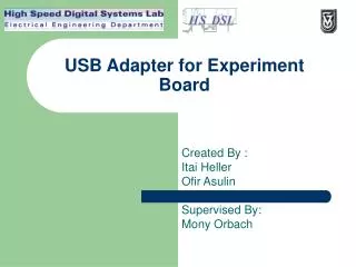
USB Adapter for Experiment Board Created By : Itai Heller Ofir Asulin Supervised By: Mony Orbach
Project Goals • Enhancing & Expanding an existing prototype circuit built on • a wire-wrap board. • Manufacturing a printed circuit in order to broaden and • improve lab experiments, adding future implementations. • The prototype is a Communication adapter designed to • connect between a PC USB Port and a Lab Experiment boards.
Existing Environment • The current device is based upon an old 8031 micro-controller with a RS-232 communication protocol. • It is necessary to advance to a more modern communication protocol in order to keep up with the PC advance, furthermore a higher data-flow rate is needed for future implementations. • The new interface must be consistent with existing environment in the lab (PC , 6 types of lab experiment devices and windows XP with VB 6.0).
Characterization of system Inputs i) Type of the lab educational device: received on installation (8bit). ii) Number of lab educational device: received from device (8 bit). iii) Random address: received from the PC (3 bit). Future implementations: iv) input Port: (8 bit )
Characterization of system Outputs i) PC’s approval for the connection with the device: On screen. ii) Approval for the receiving of the random address: Buzzer (1 bit). Future implementations: iii) output Port (8 bit)
Experiment Board (Midgam) 3 bits Confirmation (Buzzer) USB Adaptor & FPGA PC USB 1 bit 3 bits Draw Control 1 bit 8 bits 8 bits 8 bits 8 bits Board Number I/O PORT Power Stabilizer Outside Voltage Block Diagram
Block Diagram-In depth 3 bits Experiment Board (Midgam) Confirmation (Buzzer) 1 bit PC DLP USB Adaptor Cyclon FPGA USB 3 bits Draw Control Clock EPSC 1 bit Reset 8 bits 8 bits 8 bits Outside Voltage Power Stabilizer Board Number I/O PORT LM7805 2XSwitch DIP-8 RS323
Schedule • Theoretical orientation.6/4/2005-DONE • System planning:12/5/2005-DONE • Choosing and placing of components • Learning Orcad • Circuit drawing on Orcad and handing it to Ella.-DONE • Creating the circuit (with Ella) and configuration of the FPGA (in VHDL).12/6/2005 • Simulations & Debugging.12/7/2005 • Driver Writing.28/7/2005 • Implementation of the Adaptor with the experiment system.28/8/2005