Download
1 / 37
380 likes | 471 Views
Serial I/O and the HC11. Overview. General discussion of serial I/O operations Synchronous vs. asynchronous operations Baud rate vs. bit rate Transmission standards 68HC11 capabilities General description Programming and operation Readings: Text, Chapter 10.

E N D
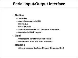
Overview • General discussion of serial I/O operations • Synchronous vs. asynchronous operations • Baud rate vs. bit rate • Transmission standards • 68HC11 capabilities • General description • Programming and operation • Readings: Text, Chapter 10
Serial Input and Output Operations • A serial data transfer moves one bit at a time between the processor and a peripheral device • A parallel data transfer moves one word at a time (often, 1 word = 1 byte) • Why use serial I/O? • Some I/O operations are inherently serial • If transmission distance is large, parallel data transmission may prove to be too expensive to implement • If using the phone system, only have the serial option! Cont..
Serial Input and Output Operations • Interfaces • Logical: performs the parallel-to-serial and serial-to-parallel data conversions • Electrical: Transforms TTL voltage and signal levels to that of the transmission medium Cont..
Serial Input and Output Operations • Direction of transmission • Simplex: data transfer in one direction only • Half duplex: transfer is bi-directional, but in only one direction at a time • Full duplex: transfer is bi-directional and can take place in both directions at the same time • Transmission timing • For serial I/O, often speak of each data packet as being a character (often ASCII) • Asynchronous: • Transmitter and receiver are not synchronized with respect to the time at which a character is transmitted Cont..
Serial Input and Output Operations • Each transmitted character is composed of data bits and framing bits 1. First, transmit start bit(s) 2. Next, transmit data bits sequentially 3. Finally, transmit stop bit(s) • The transmitter may separate characters by random amounts of time • The bit stream for data and framing bits are transmitted at a known rate • A start bit is used to synchronize the receiver to the transmitter for the reception of one character • When no data is being transmitted, transmitter output is idle (active low levels) Cont..
Serial Input and Output Operations • Synchronous: • Transmitter and receiver stay in sync at all times through the use of synchronization characters • Start and stop bits are eliminated • Data is transmitted as a continuous stream, with no indication of character boundaries • Transmission rates (This is a little confusing, and the book (p. 339) mainly adds to the confusion) • baud = “symbols per second,” named after the inventor of the Baudot telegraph code • symbol = 1 or more bits, encoded for transmission Cont..
Serial Input and Output Operations • Here's a frequency-shift-keying (FSK) example; in this case, the frequency determines 1 of 4 possible symbols (2 bits each) • bit rate: number of bits transmitted per unit time, usually stated in units of bits per second (bps) • The baud rate is not necessarily the same as the bit rate, although the terms are sometimes (incorrectly) used interchangeably • Sometimes you may need to distinguish between the bit rate for data alone, vs. bit rate including framing bits or sync characters Cont..
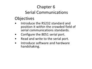
Serial Input and Output Operations • Electrical interface and transmission standards • Problems with transmission • Noise • Different ground connections • Transmission line effects (reflections) • Solutions • Line drivers not at TTL levels • EIA standard transmission circuits • Single-ended, balanced differential, unbalanced differential Line driver configurations [Sho87] Cont..
Serial Input and Output Operations • EIA standards include RS232, RS423, RS422, and RS485 • Differences in the standards include • Mode of transmission (single vs. differential) • Data transmission rates • Type of transmission line and its length
68HC11 serial communications • The 68HC11 supports both asynchronous and synchronous serial communications • SCI (serial communications interface) system provides asynchronous transfers • SPI (serial peripheral interface) system provides synchronous transfers • Both the SCI and the SPI use pins on port D to perform their transfers • SCI uses pins 0 and 1 • SPI uses pins 2-5 • Prior to performing either type of serial transfer, the interface must be configured / initialized Cont.
68HC11 serial communications • Asynchronous communication • Framing bits • Each data byte is framed with a start bit and one or more stop bits • Start bit is always 0 (idle line is always 1) • Stop bit is always 1 • Different protocols may use 1, 1.5, or 2 stop bits • HC11 always uses 1 stop bit • Data byte is transmitted LSB first • Parity • Can be used to detect single-bit errors in the data (do not consider start/stop bits) Cont.
68HC11 serial communications • Usual implementation: append 1 extra bit to the end of the data (parity bit sent after MSB) • Even parity: select the value of the parity bit to cause an even number of 1s • Odd parity: select the value of the parity bit to cause an odd number of 1s • Not directly supported by HC11 • Must be implemented in software • Peripheral chips (e.g. 8251 UART) do support it Cont.
68HC11 serial communications • Asynchronous transfers using the SCI • Ports and pins used • Port pin PD1 is the transmit line TxD • Port pin PD0 is the receive line RxD • Data is written and read from SCI data register, SCDR, at address $102F • Port is initialized by setting SCI Control Registers 1 and 2, at addresses $102C and $102D • Desired baud rate based on division factors in the Baud Rate Control Register, address $102B • Port status is reported in register SCSR, at address $102E (not $102F as in Figure 10.5!) Cont..
68HC11 serial communications • Nominally transmits 8-bit data words • Can transmit a 9th bit if desired • Software can use 9th bit for parity (parity not automatically generated or checked) Cont..
68HC11 serial communications • Configuration • Select desired baud rate -- write to baud rate register (bits SCP0-1, SCR0-2) • Select word length and wake up -- write to SCCR1 • Select interrupt operations, TxD and RxD operations, etc. -- write to SCCR2 • Transmission procedure • Poll status register or respond to interrupt (read the SCSR) • If using 9-bit data, write 9th bit (bit 8) to T8 in SCCR1 • If TDRE=1, write lower 8 bits of data to the SCDR • Receiving procedure • Poll status register or respond to interrupt (read the SCSR) • If RDRF=1, read SCDR • If 9-bit data, read bit 8 from SCCR1 Cont..
68HC11 serial communications Cont..
HC11 serial communications • Baud rate selection • Desired baud rate is specified by the combination of baud-rate preselects and baud-rate selects, in the baud rate control register • See HC 11 manual for detailed information (text only presents settings for 8 MHz clock in Figure 10.5):
HC11 serial communications • Receive errors • Overrun Error • Occurs when new character is received before previous character is read from SCDR • New character is lost • Sets OR flag in SCSR • Noise Error • Receiver samples data line at 16 times the bit rate • If samples in middle don’t match, there may be noise on the line • Sets NF flag in SCSR
HC11 serial communications • Framing Error • Occurs when an invalid stop bit is detected • May be due to baud rate mismatch, framing protocol mismatch, or noise • Sets FE flag in SCSR • SCISUBS.H *********************************************** * Subroutine to initialize(INIT) SCI for serial * communications at 8 data, no parity, 1 stop * bit. Directly compatible with TERM in * PCbug11 and F7 comm in Iasm11. * All registers returned to calling conditions. Cont..
HC11 serial communications * CEN 9/22/93 Initial release ********************************************** INIT PSHX ; Save registers PSHA LDX #REGBAS LDAA #$30 ; 9600 baud, assuming 8 MHz ; clock STAA BAUD,X ; BAUD REGISTER LDAA #$00 ; 8 data bits STAA SCCR1,X ; LDAA #$0C ; No interrupts, enable TX, ; RX, no wakeup Cont..
HC11 serial communications STAA SCCR2,X ; LDAA SCSR ; Clear RDRF, Error flags LDAA SCDR ; Clear receive buffer PULA ; Restore registers PULX RTS *********************************************** * Subroutine to receive(REC) a single character * from an initialized SCI serial device. No * echo to screen takes place. * Received character returned in ACCA. No other * registers modified. Cont..
HC11 serial communications * CEN 9/23/93 *********************************************** REC PSHX ; Save X register LDX #REGBAS ; Point to register bank NOCH BRCLR SCSR,X,$20,NOCH ; Wait for RDRF LDAA SCDR,X ; Get received character PULX ;Restore X register RTS *********************************************** * Subroutine to transmit(TRS) character from * SCI to serial connected terminal Expects * character to be displayed to be in ACCA upon Cont..
HC11 serial communications * entry. * No other registers modified. * CEN 9/23/93 *********************************************** TRS PSHX ; Save X register LDX #REGBAS ; Point to register bank TBNMT BRCLR SCSR,X,$80,TBNMT ; Loop until xmit output buffer empty ; Empty if TDRE flag in SCSR register = 1 STAA SCDR,X ; Write char to output buffer PULX ;Restore incoming X register RTS Cont..
HC11 serial communications • Synchronous transfers using the SPI • Two (or more) devices communicate via a serial bus with one device being the "bus master" and the others being "slaves" • For SPI, both devices transmit and receive one byte during each transfer • Master controls transfers by providing the clocking signals required • Advantages of synchronous communication • Faster transfers • Higher clock rates • No start/stop bits Cont..
HC11 serial communications • Disadvantages • Must provide clock signal to slaves • Useful for: • Communicating with local peripherals • Can use built-in SPI interface • Communicating with other computers or remote peripherals (network) • Usually requires special-purpose ICs Cont..
HC11 serial communications • Basic SPI operation Cont..
HC11 serial communications • SPI serial system (bus topology) Cont..
HC11 serial communications • SPI Registers SPIE SPI Interrupt Enable SPE SPI System enable DWOM Port D Wire-Or Mode (0=normal, 1=open-drain) MSTR Master/Slave Select (0=slave , 1=master) CPOL Clock Polarity 0=active-high, 1=active-low) CPHA Clock Phase Select SPR1,0 SPI Clock Rate Select Bits Cont..
HC11 serial communications • SPI Registers SPIF SPI Interrupt Request WCOL Write Collision Status Flag MODF SPI Mode Error Interrupt Status Flag DDRD5(Mater) 0 = SS input to detect mode fault 1 = SS is general purpose output Slave = always input DDRD4(Master)0 = SCK output disabled Cont..
HC11 serial communications • Master SPI operation Cont..
HC11 serial communications • Slave SPI operation Cont..
HC11 serial communications • SPI Error Handling • Mode Fault • Occurs when more than one device tries to be a master • Detected when the master’s SS input is driven low (by another node trying to be a master) • Sets the MODF flag in the SPSR register • Generates an interrupt if SPIE is set • Write Collision • Occurs when MCU attempts to write to SPDR while a transfer is taking place • Previous data is not overwritten • Sets the WCOL flag in SPSR Cont..
HC11 serial communications • Master can prevent this by checking the SPIF flag before writing to SPDR • Slave should check WCOL flag after writing to see if collision occurred • Overviewed serial communications • Interfaces • Transmission “standards” • 68HC11 implementations • SCI • 8 or 9 bit data Rx/Tx • Automatically adds start/stop bits • Uses PD0 and PD1 for receive/transmit Cont..
HC11 serial communications • Wide range of baud rate support • Use available routines in scisubs.h for “typical” interface • SPI • 8 bit data • Devices receive and transmit simultaneously • Uses PD2-PD5