Download
1 / 11
120 likes | 232 Views
This study focuses on advancing predictive modeling capabilities for space and strategic systems affected by transient radiation effects. Specifically, it addresses errors induced by high-energy ion exposures that can corrupt data in components like voltage regulators. The project involves creating radiation-enabled macro-models, exemplified by the LT1129 voltage regulator, and performing laser testing to analyze transient behaviors. Our findings emphasize the collaboration between Raytheon and ASU to enhance system design and integrate new testing methodologies effectively.

E N D
Transient Radiation Effects Behavioral Modeling David Oleksy, Electrical Engineering Hugh Barnaby, Bert Vermeire, Craig Birtcher, ASU, Stephen Buchner, NRL 2009 – 2010 Statewide Symposium Arizona Space Grant Consortium KuiperSpace Sciences / LPL, April 17, 2010
Problem Statement • Increasing sophistication of space and strategic systems • Radiation hardness demands of some missions • New predictive modeling capabilities must be developed to support system design prior to test and integration
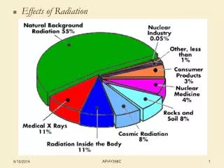
Radiation Effects of Concern • We are focused on errors caused by high energy ion exposures, which lead to single event effects and transients • In example: A memory module’s stored data can be corrupted when struck by a high energy particle • In this study: The output of a voltage regulator deviates from the nominal voltage when certain nodes are irradiated
Project Tasks Our first effort focuses on the delivery of a radiation-enabled macro-model for a Raytheon system component • Targeted component:LT1129 3.3V Voltage Regulator • Project deliverables:
Task 1 – Standard Macro-model * OUT ADJ GND SHD IN .SUBCKT LT1129 1 2 3 4 5 QPWR 51 54 52 Q1 RBASE 54 53 16100 DDARl 53 84 DX RDROP 51 1 0.4 TC=4.0E-3 RQC 1 3 106E3 VCURR 5 52 DC 0 FGND 5 3 POLY(1) VCURR 8.5E-6 0 0.097 FCL1 3 60 VCURR 0.31 RCL1 60 3 10 DCL1 60 61 DX VCL1 61 62 DC 0 ECL1 62 3 POLY(1) 5 3 2.75 0.035 FCL2 90 3 VCL1 1.0 IBSD 5 4 DC 6.0E-6 DSDP1 4 70 DX VSDP1 70 3 DC 6.2 DSDN1 71 4 DX VSDN1 71 3 DC 0.595 GSD1 3 73 72 4 1.0E-1 RSD1 73 3 1.0E4 CSD1 73 3 2.2E-9 GTV1 3 72 POLY(1) 73 3 0.78E-3 1.20E-4 RTV1 72 3 1.0E3 DSDP2 73 74 DX VSDP2 74 3 DC 2.90 DSDN2 75 73 DX VSDN2 75 3 DC 0.85 QSD 90 77 3 Q2 RSD3 77 3 1.0E1 GSD3 3 77 73 3 5.3E-2 IBEA 3 80 DC 148.7E-6 REA1 80 3 1.0E3 TC=-4.6E-3 GEA1 2 3 80 3 1.0E-6 DEAP1 2 81 DX VEAP1 81 3 DC 5.3 DEAN1 82 2 DX VEAN1 82 3 DC 0.4 GEA2 3 84 2 90 10.0 REA2 84 3 1.0E3 CFEED 84 88 1e-8 RFEED 88 90 2.0E3 DREV 5 55 DX RREV 55 3 1.0E9 DEAP2 84 85 DX EEAP2 85 3 POLY(1) 55 3 -1.0 1.0 DEAN2 86 84 DX VEAN2 86 3 DC 1.0 IREF1 3 90 DC 3.7502E-3 RREF1 90 3 1.0E3 TC=1.0E-4 GLINE 3 90 5 3 1.3E-8 GLOAD 90 3 51 1 24.6E-6 .MODEL DX D IS=8e-16 RS=0 XTI=0 .MODEL Q1 PNP IS=1e-12 BF=11400 XTI=0 .MODEL Q2 NPN IS=1e-16 BF=1000 XTI=0 .ENDS LT1129 with additions Schematics by David Oleksy with help from Bert Vermeire
Task 2 – Laser Testing Prep Photo by David Oleksy Photo by David Wright and David Oleksy
Task 2 – Laser Testing Prep • Package chip • Design test board • Order the board • Populate board • Write manual All graphics by David Oleksy
Task 2 – Laser Testing • Example of data set: • Highlighted strike locations that produce similar measurable voltage output effects Results by Stephen Buchner
Task 3 – TRE Enabled Model • Model development is in progress • Radiation strikes are simulated with directly applied spikes of current on certain circuit nodes • Simulated strikes on some nodes already match the data… Double Exp. Current Spike Hugh Barnaby Hugh Barnaby Stephen Buchner
Current Conclusions • Laser testing is an effective means of measuring transients in linear microcircuits • It is advised to consider development of a laser system as a stand-alone characterization and modeling tool • It is advised to establish collaboration between Raytheon and ASU to progress appropriately and integrate with Raytheon’s TopACT code • Laser test data used with macro-model is cheaper, quicker and more powerful. • TRE enabled macro-models allow better system design
That’s it! • Thank you for listening • Please ask any questions you may have