Download
1 / 29
300 likes | 351 Views
Explore power estimation techniques in metal rolling, including work and energy principles, hot vs. cold rolling, and the role of friction. Learn about various rolling technologies and machines used in the process.

E N D
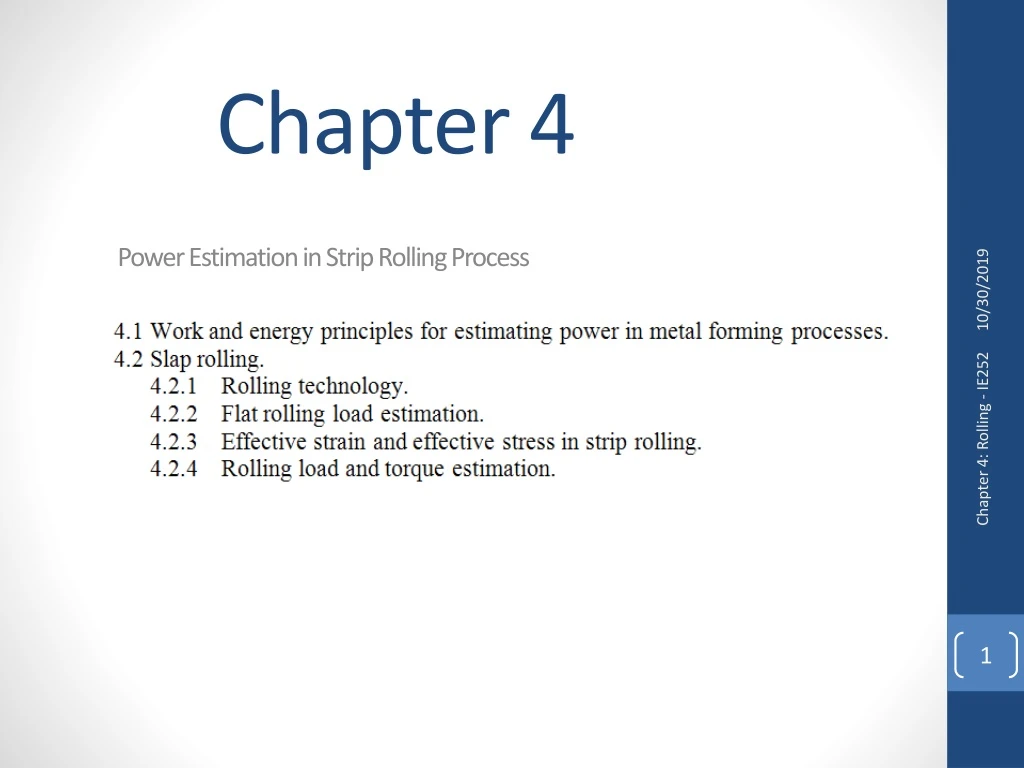
Chapter 4Power Estimation in Strip Rolling Process Chapter 4: Rolling - IE252
4.1 Work and energy principle for estimating power on metal forming processes. • The work and energy method is an approximate technique of estimating the forces/torque and power required in metal forming processes. • The technique is based on the assumption that the material is homogeneous and the friction condition is neglected in the power estimation (i.e. ideal work). • The applied force/torque assumed to be acting directly normal or parallel to cross-section area. For example, the maximum load, Pmax , applied for compressing a cylinder can be approximated as Pmax=σyield Amax , where σyield is the yielding strength and Amaxis the area of specimen at maximum strain. • The principle of approximating the force/torque required is based on equating the work of external applied force to the internal energy. The work due to external force is expressed as; Chapter 4: Rolling - IE252
4.1 Work and energy principle for estimating power on metal forming processes. Chapter 4: Rolling - IE252
4.1 Work and energy principle for estimating power on metal forming processes. Chapter 4: Rolling - IE252
4.2 Slap Rolling • 4.2.1 Rolling technology Chapter 4: Rolling - IE252
4.2 Slap Rolling • 4.2.1 Rolling technology Rolling is one of the metalworking processes that can be run as hot or cold working. The main difference between hot and cold rolling is that in hot rolling the rolling process is carried out at elevated temperature (above room temperature). While cold rolling is carried out at room temperature. Hot rolling is more important than cold-rolling process. Chapter 4: Rolling - IE252
4.2 Slap Rolling • 4.2.1 Rolling technology About 90% of all metal produced annually in the world through rolling process. Fig. 4.2 shows some of the semi finished products (e.g. structure shape, rails, bars, pipe, plates, strip,etc.) that can be produced by rolling process. Products with raw material from rolling process Chapter 4: Rolling - IE252
4.2 Slap Rolling • 4.2.1 Rolling technology Ferrous metals are usually hot-rolled while non-ferrous metals are commonly cold-rolled. Rolling products are usually used as raw material for different manufacturing processes. For example, the wire product is used to manufacture wire baskets, rods are used in manufacturing bolts and nuts. Products with raw material from rolling process Chapter 4: Rolling - IE252
4.2 Slap Rolling • 4.2.1 Rolling technology Chapter 4: Rolling - IE252 Hot rolling process starting from casting
4.2 Slap Rolling • 4.2.1 Rolling technology Flow diagram of steel making (Rolling Process) Chapter 4: Rolling - IE252 Hot rolling process starting from casting
4.2 Slap Rolling • 4.2.1 Rolling technology Flow diagram of steel making (Rolling Process) Chapter 4: Rolling - IE252
4.2 Slap Rolling • 4.2.1 Rolling technology Flow diagram of steel making (Rolling Process) Chapter 4: Rolling - IE252
4.2 Slap Rolling • 4.2.1 Rolling technology • Strain hardening is involved in cold rolling process, while it does not exist in hot rolling. Hot rolling depends on work piece temperature and strain rate and the process involves annealing condition. • Friction condition is very high between roll and work piece in cold rolling process where lubrication is necessary in such case. • Sliding friction condition exists between roll and work piece in cold rolling, while a sticking friction condition exists in case of hot rolling. Chapter 4: Rolling - IE252
4.2 Slap Rolling • 4.2.1 Rolling technology Rolling mill (machines); rolling process is carried out on a machine called rolling mill. The rolls are usually flat type when rolling flat strip, and deformed rolls in case of structure or round stripes/channels. The rolls are assembled in housing and the entire unit called rolling stand. Typical arrangement of rolls in a rolling mill. • 2-high single pass or pull over; • 2-high reversing mill; • 3-high mill; • 4-high mill; • 6- and • 12-high cluster roll mill Chapter 4: Rolling - IE252
4.2 Slap Rolling • 4.2.1 Rolling technology • Rolling mill (machines); • For example, a rolling mill have two rolls in its stands called two-roll mill. Similarly, A three-high mill has three rolls,etc. • The rolls that are in contact with the work-piece are called working rolls, while those idles and supporting the work-piece are called backup rolls. • Different roll diameters are commonly used for more support and for avoiding roll deflection, which results in defect rolling product. Chapter 4: Rolling - IE252
4.2 Slap Rolling • 4.2.1 Rolling technology • Rolling mill (machines); • In rolling mill, the working rolls are rotating in opposite direction when rolling follow in one direction. • Some of the mills have reversing working rolls for each pass (small mills). In this case, the metal rolled back and forth, while gap between the driving rolls is frequently adjusted to achieve the desired strip thickness. • One disadvantage of reversing rolls is that each reversing time requires overcoming the inertial forces which may results in fatigue stresses and decrease the life of rolling mill. Chapter 4: Rolling - IE252 cluster roll mill (type f) 6 High mill (type d)
4.2 Slap Rolling • 4.2.1 Rolling technology • Rolling mill (machines); • In rolling mill, the working rolls are rotating in opposite direction when rolling follow in one direction. • Some of the mills have reversing working rolls for each pass (small mills). In this case, the metal rolled back and forth, while gap between the driving rolls is frequently adjusted to achieve the desired strip thickness. • One disadvantage of reversing rolls is that each reversing time requires overcoming the inertial forces which may results in fatigue stresses and decrease the life of rolling mill. Reverse Mill Chapter 4: Rolling - IE252 Tandem mill
4.2 Slap Rolling • 4.2.2 Flat rolling load estimation • Assumptions: • Rolling process can be considered as a forging process, where, roll is dispaced toward a flat strip, i.e. rolling force due to roll forging. • The friction condition between roll and strip is neglected. • Rolling process can be analyzed as plan strain condition, where the strain along strip is nearly zero, i.e. wo=wf . Chapter 4: Rolling - IE252
4.2 Slap Rolling • 4.2.3 Flat rolling load estimation- Effective strain and stress in strip rolling: Chapter 4: Rolling - IE252
4.2 Slap Rolling • 4.2.3 Flat rolling load estimation- Effective strain and stress in strip rolling: Chapter 4: Rolling - IE252
4.2 Slap Rolling • 4.2.3 Flat rolling load estimation- Effective strain and stress in strip rolling: Chapter 4: Rolling - IE252
4.2 Slap Rolling • 4.2.3 Flat rolling load estimation- Effective strain and stress in strip rolling: Chapter 4: Rolling - IE252 Too small Value, neglected
4.2 Slap Rolling • 4.2.3 Flat rolling load estimation Chapter 4: Rolling - IE252
4.2 Slap Rolling • 4.2.3 Flat rolling load estimation Hence, the corrected rolling load can be expressed as follows Chapter 4: Rolling - IE252
4.2 Slap Rolling • 4.2.3 Flat rolling load estimation Chapter 4: Rolling - IE252
4.2 Slap Rolling • 4.2.3 Flat rolling load estimation Chapter 4: Rolling - IE252
4.2 Slap Rolling • 4.2.3 Flat rolling load estimation Chapter 4: Rolling - IE252 From (a & b): clearly observed rolling load and power increase with increase of strip reduction
Problems Chapter 4: Rolling - IE252