Download
1 / 20
200 likes | 339 Views
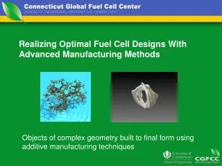
Realizing Optimal Fuel Cell Designs With Advanced Manufacturing Methods. Objects of complex geometry built to final form using additive manufacturing techniques. Today’s Mass Customization Applications. Scan-Digitize-Manufacture Patient-specific orthodontia and joint replacements

E N D
Realizing Optimal Fuel Cell Designs With Advanced Manufacturing Methods Objects of complex geometry built to final form using additive manufacturing techniques
Today’s Mass Customization Applications • Scan-Digitize-Manufacture • Patient-specific orthodontia and joint replacements • Patient-specific hearing aid shells • Athlete-specific sports shoes soles • Part, material, and process-specific cooling of molds for injection molding • Replacement of multiple-part assemblies with one piece (commercial aerospace applications) T.Bergman
Cutting Edge Layered Manufacturing Titanium cage fabricated 12/03 with selective laser melting Courtesy S. Hollister Zirconium oxide cage fabricated with ink jet printing (Zhao et al., 2002) T.Bergman
Tomorrow’s optimally-designed and manufactured fuel cell • Manufacture of truly optimal fuel cell designs • Selective catalyst seeding for optimal performance and minimum cost • Conformal geometries for bio applications • Opportunities for revolutionary system design T.Bergman
Work in Progress at UConn/Ionomem • Scale-Up of MEAs • Performance Characterization • Single Cell & Short Stack • 300 cm2 Testing • Optimization of MEAs • Material Characterization • Endurance Testing • Composite membrane (based on Nafion® and solid proton conductor) • Nafion®-Teflon®-phosphotungstic acid (NTPA) {HPA Stabilization} • Nafion®-Teflon®-zirconium hydrogen phosphate (NTZP) • Nafion®-Zirconium hydrogen phosphate (NZP) • Increased Thermal Stability (Ionic form of Nafion®) • Catalyst layer: • Optimize Proton Conduction • Optimize Mass Transfer • Diffusion layer: • Enhance Gas Transfer • Optimize Hydrophilic/Hydrophobic Regions J. Fenton
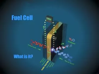
Membrane 1-2 mils Components of a PEMFC MEA Anode catalyst Pt-Ru/C 0.3 - 0.5 mg/cm2 ~ 0.6 - 1 mils Cathode catalyst Pt/C 0.3 - 0.5 mg/cm2 ~ 0.6 - 1 mils Membrane Electrode Assembly (MEA) Anode gas diffusion layer 14 - 16 mils Cathode gas diffusion layer (GDL) 14 - 16 mils J. Fenton
Cluster Network Model for Nafion® Recast Nafion® HPA secondary structure Nafion ®/ PTA Composite (NPTA) FTIR Nafion®/Heteropolyacid Composite Membranes Rationale : - Inherently high HPA conductivity at high humidities (~ 0.2 S/cm) - Induction of alternate conduction mechanisms – i.e. enhancement of proton hopping XRD J. Fenton
High Performance under Non-Humidified Conditions TCell/TA,Hum/TC,Hum, Membrane: 1mil NTPA Membrane, In-house Substrate 0.5 mg/cm2 Pt/C for cathode , 0.5 mg/cm2 Pt-Ru/C for anode 0.674 V 0.645 V Remove humidification & Lower inlet flow rates of both Cathode & Anode, 30 mV loss with Simpler System, NO humidifier required, HIGHER utilization. J. Fenton (Williams Thesis)
Conclusion • High Performance high temperature MEAs • Developed from 5 & 25-cm2 • 0.6 V @ 400 mA/cm2 (120°C, 35%R.H./1 atm) – R = 0.18 ohm-cm2 • 0.66 V @ 400 mA/cm2 (120°C, 50%R.H./1.5 atm) – R = 0.09 ohm-cm2 • Scaled up to full size – 300 cm2 • Similar Performance as elemental cell – up to 4 cell stack • Component Development • Composite membrane – high conductivity & stabilized • Catalyst structure & kinetics studies – optimized & < 1st order • Gas diffusion layer – superior than commercial at high T/low R.H. • Unique Applications • NO external humidification – High Perf. (GDL & Stoi.) • LOW Flow Rate – CO tolerance not much important J. Fenton
Under a NSF Grant, UConn Has Fabricated Ceramics for On-Site Production of Hydrogen from Natural Gas to Produce a Hydrogen Infrastructure for Fuel Cell Use. A reforming catalyst is packed into perovsite ceramic tubes to convert the natural gas into a stream containing hydrogen. The hydrogen is purified since only the hydrogen can pass through the perovsite tube walls. UConn Perovsite R. Kunz
Molten Carbonate Fuel Cells for Cogeneration Use Can be Reduced in Cost by the Development of Alternative Cathodes • MCFCs operate at a high enough temperature (650oC) to allow very efficient cogeneration and demonstrations are underway at FuelCell Energy. • The performance of a MCFC stack is limited by cathode catalytic performance. • Combined electron and oxide ion conductors may enhance that catalytic activity. • Such conductors have been researched for use in solid oxide fuel cells. • Some of these materials have shown stability in the MCFC environment and should be evaluated for their catalytic properties. R. Kunz
Cogeneration Fuel Cell Power Plants Can be Developed to Efficiently Use Agricultural Wastes as the Fuel Source • Ethanol can be made from agricultural materials such as corn stalks, straw, wood, grasses and waste papers by a fermentation process. • Methane can be made from such materials by a gasification process. • Traditional processes to make useful products from wastes require purification; e.g., the distillation of water from an ethanol/water stream. • Fuel cells can tolerate some impurities in fuels; e.g., some fuel cells need water. • Wastes are frequently too low in value to ship long distances. • Fuel cells can locally consume impure products of processed waste to generate both electricity and heat for on-site use. R. Kunz
Models Science Experiments • Science Links - Wilson K. S. Chiu • MODELS ASSISTED BY EXPERIMENTS • Construct hierarchical modeling methods from nano-to-systems using teraflop computing capabilities and optimized computational and simulation algorithms. • Design fuel cell validation system. • REGEN Science: reversibility, recharging dynamics, severe environments, cycling, fabrication and manufacturing. • COGEN Science: thermal management, transient operation, recovery of co-products, heat exchange, optimization, scaling. • SSGEN Science: fuel consumption, thermal management, anode / cathode nanostructural design, fabrication and manufacture, accelerated characterization.
Defect Fused Silica Preform Furnace Core 5 mm Understanding Hole Pattern Formation DuringMicrostructured Optical Fiber DrawWilson K. S. Chiu (UConn) and David J. DiGiovanni (OFS Labs) Structures of Interest: Draw Process:
CVD Hermetic Coating Chamber Transport Phenomena in the Chemical Vapor Deposition ofHermetic Optical Fiber CoatingsWilson K. S. Chiu, UConn Computational Modeling & Design Film Growth & Characterization
Integrated Fuel Cell Systems Engineering Design and Manufacturing Research Center • Educational Efforts: • Multi-University Integrated and Modular Approach to Fuel Cell Science & Engineering Education - The Vision • Overcomes the difficulties associated with large scale curriculum changes • Allows for integration of fuel cell technology education in current curriculums of Mechanical Engineering, Chemical Engineering, Engineering Mechanics, Chem, etc. • Integrated as part of electives • Access to the Experts (ATTE) – The Means • Allows for access to technology and experts at other universities that would otherwise not be available at one university • Expands opportunities for learning and research • Interdisciplinary approach to education • Distributed Learning – The Methods • Interactive video • Web based • Faculty-Student Exchange • EDS e-engineering
Integrated Fuel Cell Systems Engineering Design and Manufacturing Research Center • Underrepresented Institution: • University of Puerto Rico System • Carlos R. Cabrera, Chemistry, UPR Rio Piedras • Vijay K. Goyal-Singhal, Mech Engr., UPR Myaguez (UPRM), collaboration with Pratt/UConn & EDS • Ricardo Roman, Vice Chair of the UPRM Sch of Engin. Industrial Advisory Board, Hamilton Sundstrand PR Electronics in Santa Isabel • Interactions • Catalysts • System engineering (EDS e-engineering) • Distributed learning • Technology, Industrial, & Fabrication Implementation • PR Economic Development
United Technologies Fuel Cells, United Technologies Research Center • UCONN • Global Fuel Cell Center • Institute for Interdisciplinary Engineering, • Design and Computing • Manufacturing Res. & Development Group • IMS • UPRM • UTC-Hamilton Sunstrand interaction • Mech. E. and Chem. E. fuel cell research • e-engineering effort • Virginia Tech • Interdisciplinary Materials Institute • Materials Response Group • Gate Center Systems Engineering Materials Modeling and computing Sensing and control • ASME • J. Fuel Cell Science and Technology • Intl. Conf. Fuel Cell Sci. & Tech. Education • Army Engineering Design and Manufacturing Research Center for Fuel Cell Systems Design Cost • Fuel Cell Energy Manufacturing Producibility Legal/Policy Durability Fuels, catalysts Performance Development Schedule • Harvard • Kennedy School • Yale • S. Environmentl Sci • demonstration unit • GenCell • Navy • Acumentrics • Ztek • Connecticut Clean Energy Fund • Hamilton Standard • Electric Boat • Proton Energy Systems ERC Information Technology Enterprise Enabling the virtual ERC via e-science and e-engineering
Key enabling technologies: Grid-based distributed collaborative framework Data Grid overlayed on Computational Grid Computational Grid, including NPACI/TerraGrid Access Grid