Download

1 / 34
340 likes | 572 Views
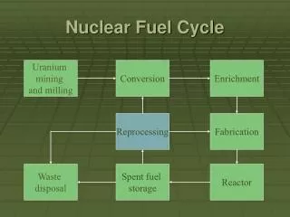
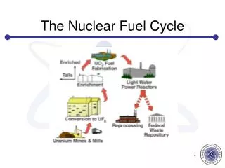
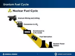
Fuel Cycle Analysis Methods for Advanced Reactor Concepts. Yunlin Xu T.K. Kim D. Tinkler T.J. Downar Purdue University Sept. 12, 2001 The 2001 ANS International Topic Meeting on Mathematics and Computation. Content. Motivation Depletion Code system Verification

E N D
Fuel Cycle Analysis Methods for Advanced Reactor Concepts Yunlin Xu T.K. Kim D. Tinkler T.J. Downar Purdue University Sept. 12, 2001 The 2001 ANS International Topic Meeting on Mathematics and Computation
Content • Motivation • Depletion Code system • Verification • Application on SBWR • Further Improvements
Motivation • NERI/DOE projects at Purdue • SBWR: evolutionary “Generation III+” • HCBWR: revolutionary “Generation IV” • We need a ‘depletion code system’ for • Neutonic designing: • Fuel cycle analysis • Safety analysis (throughout core life)
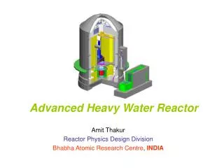
SBWR Reactor Vessel • Total Height 24.6 m • Internal Diameter 6.0 m • Fuel Length 2.74 m • Chimney Height 9 m
SBWR Containment (GE) • Gravity Driven Coolant System (GDCS) • Automatic Depressurization System (ADS) • Passive Containment Cooling System (PCCS) • Suppression Pool
HCBWR--principle FBR HCBWR LWR
HCBWR- Purdue/BNL design • Tight lattice • hard spectrum • long cycle length • Thorium as fertile • negative void coefficient all through the cycle
T/H code (RELAP /TRAC) Lattice Code (HELIOS /CASMO) Neutron Flux Solver (PARCS) Σ Φ GENPXS Cross Section Library (PMAXS) Depletion Code (DEPLETOR) Basic Depletion Code system
Gadolinium pin BP1 BP2 The octant of fuel assembly HELIOS • HELIOS is a comercial (Studsvik Scandpower) lattice physics code for solving Boltzmann equation with fine energy group, heterogeneous, two-Dimensional models of the fuel lattice • HELIOS uses consistent fuel assembly homogenization and energy group collapsing methods to produce few group cross sections at all fuel assembly conditions throughout the burnup cycle.
The PMAXS file structures GENPXS and PMAXS • GENPX read the outputs of HELIOS and generate PMAXS files • PMAXS tabulates the XS’s of the base state and the derivatives or difference of XS of the branches and related information
Fuel temp. Tf1, Tf2… Fuel temp. Tf1, Tf2… mod temp. Tm1, Tm2… mod temp. Tm1, Tm2… Mod. den. Dm1, Dm2… Mod. den. Dm1, Dm2… Soluble B. ppm1, … Soluble B. ppm1, … Control rod … Control rod … 0GWD/T 1GWD/T 2GWD/T 3GWD/T 4GWD/T 5GWD/T Base state and Branches Base state Branches
PARCS Purdue Advanced Reactor Core Simulator A Multidimensional Multigroup Reactor Kinetics Code Based on the Nonlinear Nodal Method Under NRC Contract T. J. Downar etc
PARCS Validation • Pressurized Water Reactor: • Reactivity Initiated Transients (CEA, etc.) • OECD TMI Main Steam Line Break (PARCS coupled to RELAP5 and TRAC-M) • Boiling Water Reactor • OECD Peach Bottom Turbine Trip Benchmark • OECD Ringhalls Stability Benchmark (Ongoing)
D2NIR P2DIR PARCS RELAP /TRAC DEPLETOR Q Q PDMR RDMR Thermal Hydraulics Field Nuclide Field/ Burunup T,ρ T,ρ Neutron Field Thermal Hydraulics Input Depletor Input Neutronics Input Coupling of Code System
RELAP/TRAC PARCS DEPLETOR PREPROC SCANINPUT READINP depl INPUTD CHANGEDIM y depl CHANGECOMI n D2NIR(1) INITIAL P2DIR(1) P2DIR(2) D2NIR(2) XSB INIT y R(T)DMR(1) PDMR(1) extth n y PDMR(2) P2DIR(4) D2NIR(4) depl n P2DIR(2) D2NIR(2) XSB SSEIG R(T)DMR(2) PDMR(2) R(T)DMR(3) PDMR(3) n DEPLETION y End EOC n n done Thconv n n y y y D2NIR(3) depl P2DIR(3) EOC y End End Coupling of Code System
PARCS DEPLETOR Read inputs Read inputs Exchange ID Initialize PVM Initialize PVM Nodalization Calculate XS XS & Derivatives Receive XS Send XS Neutron Flux Calc Burnup Clac Flux & XS Send Fluxes Receive Fluxes EOC EOC END END Algorithm for Depletion code system
PARCS Cross Section • The Cross Section representation used in PARCS Where Σr: XS at reference state ppm: soluble boron concentration (ppm) Tf: fuel temperature (k) Tm: moderator temperature (k) D: moderator density (g/cc)
Burnup and History Calculation in Depletor Burnup Distribution. ΔB(i): burnup increment of ith region ΔBc: Core average burnup increment G(i): the heavy metal loading in ith region Gc: total heavy metal loading in the core P(i): Power in ith region Pc: Total power in core. History( moderator density)
History 1 History 2 Burnup Multidimension linear interpolation
No branch One branch x0 xr x1 x0 xr More than One branch for(ppm,Tf,Tm) x xi xi+1 x0 xr x xi x0 xr Reference XS and Derivatives
More than Two branches for D x x xi xi+1 x0 xr xi+2 xi xi+1 xi+2 x0 xr Two branches for D x1 x2 x0 xr Reference XS and Derivatives
Gadolinium pin BP1 BP2 The octant of fuel assembly Verification • Problem 1: Single Assembly with reflective B.C. Comparison with HELIOS Maximum Difference 2×10⁻⁵
Verification • Problem 2 Checkerboard small core with vaccum B.C. Compared with MASTER (KEARI) Maximum Difference 0.3%
600 MWe SBWR Design Fresh fuel, 69 Once burned Fuel, 69 Twice burned Fuel, 45 • Total 732 Fuel Assemblies
Fuel Assembly Design (GE 8x8)(8 Gd Rods) • Percent Enrichments (3.95 wt% average) • 2.4 • 3.3 • 3.7 • 4.2 • 5.3 • 5.6 • Gd (1.8)
Height 24.447 Length 22.324 12082 24.447 208 0011 Turbine Side 108 22.324 206 109 191 19.364 196 011 0111 101 5.253 19.060 194 102 17.46 013 012 1.075 190 014 0141 FW Tank 104 015 189 105 15.996 188 016 0161 9.062 210 017 212 211 213 243 0021 6.934 6.934 311 313 317 377 315 … 018 262 261 263 260 293 0181 3.750 … 312 310 314 316 376 3.523 134,135,137,140,144 2.146 124 0.0 11242 RELAP5 Model • Currently uses 63 Core channels • Models Vessel Only • From Cold to Hot Leg • Inlet: Feedwater Tank • Outlet: Turbine Side • Similar Models built for 200 and 1200 MWe
Neutronics to TH Mapping 1 1 1 1 1 1 1 1 1 2 2 3 3 3 1 1 1 5 7 8 8 9 10 9 1 1 5 7 12 14 14 15 13 16 13 1 1 6 12 12 19 20 19 18 17 18 17 1 1 6 11 26 25 23 24 23 22 21 22 21 1 1 6 11 33 27 28 27 28 29 30 29 30 32 1 5 12 26 27 36 37 36 38 34 34 39 40 35 1 1 7 12 25 28 37 44 43 41 34 34 41 42 35 1 5 12 19 23 27 36 43 49 48 45 47 45 46 45 1 1 7 14 20 24 28 38 41 48 54 50 51 50 51 52 1 2 8 14 19 23 29 34 34 45 50 56 56 57 58 55 1 2 8 15 18 22 30 34 34 47 51 56 56 58 57 55 1 4 9 13 17 21 29 39 41 45 50 57 58 64 63 62 1 4 10 16 18 22 30 40 42 46 51 58 57 63 61 60 1 4 9 13 17 21 31 35 35 45 53 55 55 62 59 59 • 856 Neutronics Channels • 732 (Fuel), 124(Reflector) • 63 TH Fuel Channels, 2 Bypass
Other Related Works • Used for 200MW and 1200 MW SBWR design • Used for HCBWR analysis • Used for Ringhalls Benchmark problem • Successfully treat the history effect • VIPRE as a T/H solver for Depletion system • An EPRI code, with steady state option
Further improvements • Predictor-corrector Time integration method • Microscopic depletion?