Download
1 / 57
570 likes | 762 Views
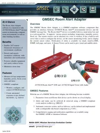
FOLDER MIRROR. Intermediate focal plane. ECHELLE GRATING TURRET. CRYOSTAT ENTRANCE. Off axis parabola. CALIBRATION GAS CELL. Off axis parabola. CROSS DISPERSION UNIT. FOCAL PLANE WHEEL. -ADC -IMAGE SLICER -SLIT APERTURES. Detector. CAMERA (Three Mirrors+ Corrector ).

E N D
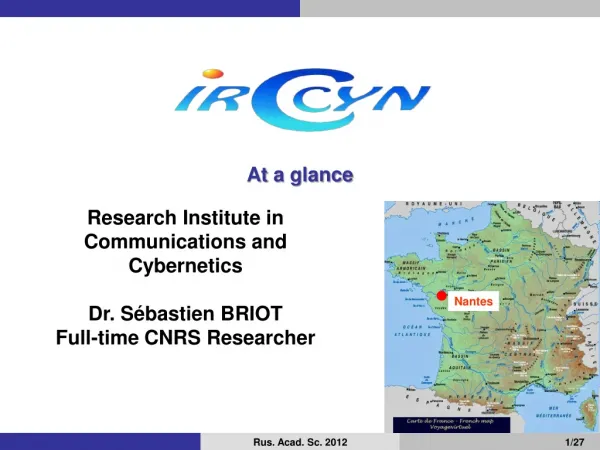
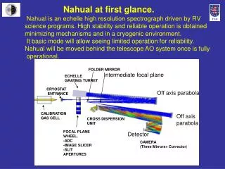
FOLDER MIRROR Intermediate focal plane ECHELLE GRATING TURRET CRYOSTAT ENTRANCE Off axis parabola CALIBRATION GAS CELL Off axis parabola CROSS DISPERSION UNIT FOCAL PLANE WHEEL. -ADC -IMAGE SLICER -SLIT APERTURES Detector CAMERA (Three Mirrors+ Corrector) Nahual at first glance. Nahual is an echelle high resolution spectrograph driven by RV science programs. High stability and reliable operation is obtained minimizing mechanisms and in a cryogenic environment. It basic mode will allow seeing limited operation for reliability. Nahual will be moved behind the telescope AO system once is fully operational.
Nahual at first glance. PERFORMANCE HIGHLIGHTS • Science Modes. Supplied with the grating turret. • High resolution 1. Grating 32.2 lin/mm at 63º (R=41582). Almost complete J,H and K coverage. • High resolution 2. Grating 41.6 lin/mm at 76º (R=84969). Partial J,H and K coverage. • High resolution 3. Grating 31.6 lin/mm at 76º (R=84969). Partial J,H and K coverage. • Low resolution mode. Flat mirror instead of echelle. J (R=1500), H (1000) and K (500). • Spectral performance • 80% of the incident light from the slit on the • detector in two pixels. • Resolution element. Two pixels • Peak efficiencies for the HR mode 42% • Mean efficiencies for the LR mode 53% • These efficiencies are without the detector • Focal plane aperture. • For the seeing limited mode 0.525”x0.6125” • For the AO mode 0.175”x 1.84” arc sec • Other main characteristics • Plate scale 0.175” arc sec/pixel • Atmospheric Dispersor Corrector unit • Calibration Gas Cell unit • Image slicer for seeing limited mode • IR slit viewing unit for pointing
Nahual Optical Design 3rd NAHUAL meeting Dornburg/Saale GTC TELESCOPE NAHUAL Ernesto Sánchez-Blanco Eduardo Martín Eike Guenther
Summary • Introduction • Requirements • Baseline optical design • -Optical subsystems and performances • -Atmospheric dispersor corrector trade off. • -Cross dispersion unit trade off • Nahual Upgrade study • Optical Management • Current phase. Scope and schedule • Next phase. Scope and schedule • Update to optics cost • Work in progress
INTRODUCTION • Nahual evolution path. Current Design for first light. IAC 2006 Improving image quality Double Pass Cross Dispersion (Two prisms) 2Kx2K detector F3.5 Camera First Design. Tauttenburg 2005 Single Pass Cross Dispersion 2Kx2K detector F3.5 Camera • Nahual baseline design will start operation in a seeing limited scenario Untill the GTC-AO system is available. Nahual Upgrade for AO operation. Double Pass Cross Dispersion (could be increased: Three prisms) Change to 4Kx4K detector (Not a gain) Change to F7 Camera (Not a gain)
REQUIREMENTS I • Maximize flux entrance for seeing limited operation. Minimum 0.525”x0.525”. (current design allows a 0.525”x0.6175” aperture) • Maximize spectral stability (minimize mechanisms). • Spectral range: J,H and K bands (goal to include Y band) • Resolution: Above 40000 (goal 75000). K BAND H BAND 2.4002 MICRONS 2.3275 MICRONS 1.9695 MICRONS 1.8290 MICRONS 1.7865 MICRONS J BAND 1.4770 MICRONS 4Kx4K Detector 1.3965 MICRONS 1.3715 MICRONS 1.129 MICRONS
REQUIREMENTS II • Optimize detector. (use 2 pixels per spectral resolution element) • Plate scale at detector 0.175” arc second per resolution element (2 pixels). • The telescope provides a F#15.6 (circumscribed pupil, or F17 in inscribed pupil. • 2Kx2K HgCdTe Hawaii Detector with 18 micron pixels. • Nominal spectral resolution performance without AO system.
BASELINE OPTICAL DESIGN FUNCTIONAL CONCEPT: white pupil FIRST STAGE: HIGH DISPERSION SECOND STAGE: CROSS DISPERSION FP1 FP2 ECHELLE FP3 CROSS DISP CAM OAP3 FLD1 OAP1 OAP2 FP: Focal plane OAP: Off axis parabola FLD: Folder mirror
BASELINE OPTICAL DESIGN: CURRENT DESIGN LAYOUT FLD1 FP2 ECHELLE TURRET OAP1, OAP2 CRYOSTAT ENTRANCE FP1 P3 OAP3 CROSS DISP FP3 CAM (Three Mirrors+ Corrector) FP: Focal plane OAP: Off axis parabola FLD: Folder mirror
BASELINE OPTICAL DESIGN: DESIGN SUMMARY I • For GTC Nasmyth platform. • F15.6 beam from telescope, seeing limited or AO corrected • PRE-FOCAL PLANE • Atmospheric Dispersor Corrector • Image slicer • Gas cell calibration unit • AUXILIARY SUBSISTEMS • IR guiding unit for object pointing and tracking • Telescope A&G unit for VIS pointing. • Telescope Instrument calibration module for spectral flat field and low Res spectroscopy .
BASELINE OPTICAL DESIGN: DESIGN SUMMARY II • SPECTROGRAPH • The spectral resolution element is in two pixels. • Collimator/Echelle pupil/Camera • Focal length 1700mm. • Off axis parabola, F# 15.6. • Estimated transmission 97% (without echelle). • Echelle Pupil • Size 109 mm • Standard echelle sizes are 128mmx254mm and 204mmx410mm depending on the grating (blazed at 63º or 76º). • Folder mirror/Second stage collimator • Focal length 1700mm • Refractive, F# 15.6. • Estimated transmission 97%
BASELINE OPTICAL DESIGN: DESIGN SUMMARY II • Cross dispersion/white pupil • Double pass design. Needs a mirror. • Can accommodate up to three prisms. • Estimated transmission 83% • Camera • Focal length 381.4mm (F#=3.5) • Three mirrors, one spherical and two aspherics. One lens as corrector • Estimated transmission 91% Mechanisms within the cryostat • Focal plane wheel with fixed positions. • Echelle wheel, with a position for each grating plus one mirror (4 positions).
BASELINE OPTICAL DESIGN: PERFORMANCE SUMMARY • Science modes. • High resolution 1 (41000). Almost complete J,H and K coverage. • High resolution 2 (85000). Partial J,H and K coverage. • High resolution 3 (85000). Partial J,H and K coverage. • Low resolution mode. J (R=1500), H (1000) and K (500). • Image quality • 80% of the energy arriving at the detector from the slit will fall on two pixels. • Transmission (rough estimation) • 42% for the first light design
ATMOSPHERIC DISPERSOR CORRECTOR UNIT I. • The ADC unit shall correct the differential atmospheric refraction effect for the • J,H and K bands. • Top. Refraction dispersion • at 81º of elevation • Left. Refraction effect for • different elevations
ATMOSPHERIC DISPERSOR CORRECTOR UNIT II. • Requirements: The image on the entrance slit will not have chromatic • aberrations larger than 0.06” arc seconds to allow the observation of • double or multiple science targets from zenith of 50º. • Trade Off analysis was done regarding the following criteria. • Adjustable unit (one mechanism required). • Fixed unit (an error of correction in requirements within an elevation range. • Three designs were worked (two warm and one cold).
Photon flux per nanometer per second per squared arc second at the instrument focal plane Telescope emissivity=0.1 ADC emissivity=0.15 Sky emissivity at K=0.134 at 230Kelvin ATMOSPHERIC DISPERSOR CORRECTOR UNIT III. • Adjustable versus fixed unit. • Mechanism issues. • Emissivity for continuous units • The preference of the trade Off result is to have a fixed cold ADC removable • unit in the focal plane wheel.
ATMOSPHERIC DISPERSOR CORRECTOR UNIT IV. • Proposed concept. • Cold within the cryostat. • To be assembled in a cylinder 25mmx25mm at the focal plane wheel.
ATMOSPHERIC DISPERSOR CORRECTOR UNIT IV. • ADC Performance. • From 0º to 21º no ADC in the optical path. • Start operation at 21º of elevation. Insert ADC. • End of the correction range within requirement 51º. • ADC Performance at 21º (left), 39º (center) and 51º (right). • The circle is the airy pattern at 1.5 microns (50 microns diameter) • Extreme wavelengths are 1.13 and 2.42 (J and K band edges).
ECHELLE DISPERSION UNIT. High Res mode. Spectral coverage I • Three gratings with fixed positions are considered plus a mirror for low • resolution (cross dispersion) spectroscopy. • One grating at R=41000 • Two gratings at R=85000
ECHELLE DISPERSION UNIT. Spectral coverage II a=63º (at litrow) b=+-2.76º are the edges of the detector d=23.2-1 mm/lin grating lines per milimeter n= diffraction order.
ECHELLE DISPERSION UNIT. Spectral coverage III • Efficiency through the field for a single • order • On the top wavelenght coverages • On the left experimental results for • grating 23.2 lin/mm at order 39 (K band) • Peak efficiency 80% (variable with order).
ECHELLE DISPERSION UNIT. Spectral coverage IV • Bottom: Relative envelopes • for different orders normalized • at the peak. • Top: efficiency at J band in • Order 80. • As we move to higher orders • The peak efficiency decrease • Quotation: Zerodur gold coated • 63º blazed (128mmx254mm) • 48.200 euros • 76º blazed (204mmx410mm) • 79.500 euros
CROSS DISPERSION UNIT I. Trade Off analysis • Required spectral dispersion • 18+2 pixels between the closest adjacent orders (32-33 of K band). • This allows a minimum point source FOV of 0.525”x0.525” arc seconds • 7 options were analyzed, in single, double pass, symmetrical and • non symmetrical prisms.
CROSS DISPERSION UNIT Trade Off summary. Analyzed Options
CROSS DISPERSION Trade Off summary.
CROSS DISPERSION UNIT II • Benefits of the double pass design • Twice the dispersion of single pass (with the same number • of prisms) • Better AIV process • Upgradeable number of prisms and more room available Two ZnSe prisms and a mirror Or two prisms, with one silvered side. • Problems of the double pass design • Slightly larger mirrors in the camera • A light astigmatism is introduced because the path is not exactly symmetric.
CROSS DISPERSION UNIT III • 23 pixels between the orders 32 and 33 allowing a 0.61”x0.525” FOV with • two pixels left dark before starting with the next order Two prisms double pass coverage
CROSS DISPERSION UNIT IV • Quotations: • Per ZnSe prism blank: 22.400 EU/blank • Per ZnSe prism manufacture and coating: 15.000 EU/piece
2.4 MICRON 2.3 MICRON 1.9 MICRON 1.8 MICRON 1.5 MICRON 1.4 MICRON 1.25 MICRON 1.2 MICRON 1.05 MICRON 1 MICRON LOW RESOLUTION MODE. Spectral coverage I • Select the mirror instead of the echelles • in the grating turret. • Dispersion is due to the ZnSe prisms. • Bottom: Spot diagram of the • dispersion due to the ZnSe • Prisms alone.
LOW RESOLUTION MODE. Spectral resolution • Bottom: Resolution considering an aperture of 0.175” (two pixels). • The current satandard aperture is 0.612” (7 pixels) wide. For optimum performance a new aperture/slicer would be required for this mode. • Resolution summary • (2 pixels) • J band 1500 • H band 1000 • K band 500
LOW RESOLUTION MODE. Image quality • Within requirements for the full J, H and K bands. • Significant degradation out of these bands • Image quality • (Box is 2 pixels wide) • Circles are Airy disk • On Top the wavelengths
CAMERA. Off axis aspherical. Centered sphere. ZnSe corrector. Spherical surfaces 80mm diameter 25mm thickness Off axis aspherical.
CAMERA. Mirror size M1:280x 220 M2:180x 150 M3:280x 220 • Maximum size did not increase relative to the original design. • No vignetting in J,H and K. • Light vignetting out of these bands • Quotations: • Pending contacts with manufacturers
J BAND H BAND IMAGE QUALITY I. K BAND • Good unvignetted image quality in • J,H and K bands (two prisms double pass) • Worse image in I band. To be optimized • in the next iteration.
IMAGE QUALITY II. Box size is 2 pixelsx2 pixels Circle: Airy disk K BAND EER 80%=16.2 microns K BAND EER 80%=15.6 microns EER 80%=16.9 microns
K BAND IMAGE QUALITY II. Enclosed energy in two pixels • Convoluted slit with the psf (geometrical + diffraction). • J and H bands over 80% in two pixels • K band 76% EES in two pixels
UPGRADE PATH GTCAO NAHUAL ADC GTC CASSEGRAIN FOCUS K SYSTEM DERROTATOR DM MIRROR NAHUAL GTC ADAPTIVE OPTICS CORRECTOR
UPGRADE PATH • NAHUAL WILL BE READY TO BE USED WITH AO GAINING S/N AND SPATIAL RESOLUTION AS SOON AS THE TELESCOPE AO IS AVAILABLE. • We can remove Nahual ADC. • Changing the image slicer by a single “long slit” (0.175”x 1.837”). • We leave room to allocate a third prism in the cross dispersion unit. • EXPECTED PERFORMANCES ARE STILL TO BE EVALUATED • The single object will cover an area about (0.175”x0.175”) against the 0.525”x0.615” of the seeing limited aperture. This is a factor 5 regarding S/N gain due to sky background. • BUT… • The AO system will loose light through its path (83% transmission). • The AO system is warm, so at the K band an increase of emissivity (around 0.25) for the full system is expected. • So the final increase in s/n will be lower (probably a factor 2 or 3).
UPGRADE PATH • RESULTS OF THE ANALISYS OF UPGRADING WITH A NEW DETECTOR AND CAMERA. ¿WHY IS NOT USEFULL? • Original idea was to use the grating of R=40000 at double resolution changing the detector in a 4Kx4K, doubling the camera focal length and reducing the slit aperture to half the current one (to 88 mas). F7 CAMERA 4KX4K DETECTOR Design originally done to consider future envelopes needs
UPGRADE PATH • All the concept is right considering we are able to maintain the spectral resolution element (the image of the slit) in two pixels. • But that is the problem. The diffraction of the spot at K band does not allow to put all the light in two pixels. Increasing the camera focal length has to be discarded. First Light Design. F3.5 camera Upgraded Design. F7 camera Boxes are 2 pixels wide. The slit is projected geometrically in a bit less than two pixels. Circles are the Airy disks at the shown wavelengths (K band edge).
UPGRADE PATH • Real^2= Slit Projection^2+ Psf aberration^2+diffraction^2 • With the current camera, the heaviest contribution is that of the Slit projection. Real=41 microns for 36 microns in two pixels. • 31 microns, is the geometrical projection of 175 mas slit on the detector. • 18 microns, are the geometrical aberrations (in 1 pixel aprox). • 20.5 microns is the Airy disk diameter. (K band edge) • But if we reduce the slit to 88mas, and double the camera focal lenght twice to sample this aperture with two pixels, the values will be Real=54 microns. • These are exactly 3 pixels. • 31 microns, is the geometrical projection of 88 mas slit on the detector. (half slit but double camera focal lenght) • 18 microns, are the geometrical aberrations (in 1 pixel aprox). (this is a reasonable value we could obtain in a more optimized design) • 41 microns is the Airy disk diameter. (the Airy is doubled in size on the detector, because we doubled the camera focal lenght)
UPGRADE PATH • CONCLUSIONS • Upgrading with a longer focal length camera results in a limited performance. • Upgrading just with a detector has the following problems. • Severe vignetting could be unavoidable with the current anastigmatic design. • Large marginal angles (twice the current ones) will be responsible of low diffraction efficiencies in a single order within the new detector area. • Considering the cost of this upgrade with the benefits, it seems not to be worth doing them.
OPTICAL MANAGEMENT: CONCEPTUAL DESIGN PHASE • Schedule September 2005-September 2006 • Resources: 360h for optical design • SCOPE for the conceptual optical design. • The idea is to have a realistic proporsal from the point of view of manufacturing, cost and that meets the scientific requirements. All the work has to be documented to create and archive and define subsystems and interfaces. • The scope is planned in a series of documented tasks (next slide).
OPTICAL MANAGEMENT: PRELIMINARY DESIGN PHASE • Schedule to be confirmed: • September 2006-September 2007 • Resources: 540h for optical design • SCOPE for the preliminary design. • Every aspect of the design will be modeled or tested to guarantee that the solution will be ready for final manufacturing drawings. • Manufacture contacts with more than one supplier should be done.
OPTICAL MANAGEMENT: OPTICS COST
WORK IN PROGRESS • Scope: • To have a complete conceptual design well documented in • September of 2006 regarding the optical design. • Tasks under progress but not ready for today. • Image slicer design. • Image quality error budget (fabrication and alignment tolerances). • Camera and OPAs manufacturer contact and quotations
IMAGE SLICER I. Seeingstatisticsat La Palma • FWHM at V band it the GTC site. • 50% of the time the seeing is under 0.69” arc seconds. • 80% of the time the seeing is under 0.9” arc seconds.