Download
1 / 168
1.69k likes | 1.77k Views
AUTOMOTIVE ENGINEERING. UNIT 2 TRANSMISSION AND DRIVE LINE. TRANSMISSION & DRIVELINE. TRANSMISSION SYSTEM Chief function of the device is to receive power at one torque and angular velocity and to deliver it at another torque and the corresponding angular velocity.

E N D
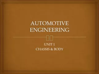
AUTOMOTIVE ENGINEERING UNIT 2 TRANSMISSION AND DRIVE LINE
TRANSMISSION & DRIVELINE TRANSMISSION SYSTEM • Chief function of the device is to receive power at one torque and angular velocity and to deliver it at another torque and the corresponding angular velocity.
REQUIREMENTS OF TRANSMISSION SYSTEM 1. To provide for disconnecting the engine from the driving wheels. 2. When the engine is running, or more, according to the relative size of engine and weight of vehicle to enable the connection to the driving wheels to be made smoothly and without shock. 3. To enable the leverage between the engine and driving wheels to be varied. 4. It must reduce the drive-line speed from that of the engine to that of the driving wheels in a ratio of somewhere between about 3:1 and 10:1 5. Turn the drive, if necessary, through 90° or perhaps otherwise re-align it. 6. Enable the driving wheels to rotate at different speeds. • Provide for relative movement between the engine and driving wheels. CLUTCH • The clutch is housed between the engine and transmission where it provides a mechanical coupling between the engine's flywheel and the transmission input shaft. • The clutch is operated by a linkage that extends from the passenger compartment to the clutch housing. • The purpose of the clutch is to disconnect the engine from the driven wheels when a vehicle is changing gears or being started from rest. • Disengaging the clutch separates the flywheel, the clutch plate and the pressure plate from each other. • The flywheel is bolted to the end of the crankshaft and rotates with it. • The clutch plate is splined to the gearbox in order for both to rotate together and the pressure plate clamps the clutch plate to the flywheel.
When the pressure is released by depressing the clutch pedal, the crankshaft and gearbox input shaft rotate independently. • When the foot is taken off they rotate as one. REQUIREMENTS OF A CLUTCH The clutch must 1. Pick up its load smoothly without grab or clatter. 2. Have a driven disc of low moment of inertia to permit easy shifting. 3. Damp out any vibration of the crankshaft to prevent gear clatter. 4. Require little pedal pressure to operate it. 5. Be easy to adjust and service. 6. Be cheap to manufacture.
BASIC PRINCIPLE OF THE FRICTION TYPE CLUTCH • To understand the working principle of clutch, let’s take two sanding discs, first one driven by a power drill corresponds to the flywheel of a car, driven by the engine. • If a second sanding disc is brought into contact with the first, friction makes it revolve too but more slowly. • But when the second disc pressed against the first disc which is connected to the power drill, as the pressure increases the two discs revolve as one. This is how a friction clutch works.
TYPES OF CLUTCHES • MULTI COIL SPRING SINGLE PLATE CLUTCH • DIAPHRAGM SPRING SINGLE PLATE CLUTCH • MULTIPLATE CLUTCH • CENTRIFUGAL CLUTCH • SEMI - CENTRIFUGAL CLUTCH • MULTI COIL SPRING SINGLE PLATE CLUTCH CONSTRUCTION • In this clutch, the coil springs force the pressure plate forwards to clamp the driven plate between it and the rear face of the flywheel. • Three lugs extend rearwards from periphery of pressure plate both to rotate the pressure plate and to cause it to rotate with the rest of the assembly. • The driven plate of course is splined onto the shaft.
There are three release levers pressing the coil springs at the outer end. The inner ends of the levers can be forced forward by means of thrust bearing made of graphite and slide along the clutch shaft when clutch pedal is depressed. • The driven plate mounted between flywheel and pressure plate makes the clutch shaft to rotate to transmit power. • It has the clutch facing made of friction materials around the periphery of disc. WORKING • When the clutch is engaged, the clutch plate is gripped between the flywheel and pressure plate. • The friction linings are on both sides of clutch plate. Due to friction between flywheel, clutch plate and pressure plate, the clutch plate revolves with the flywheel. • As clutch plate revolves the clutch shaft also revolves. Thus, engine power is transmitted to the clutch shaft. • When the clutch pedal is pressed the pressure plate moves back against the spring force and clutch plate becomes free between flywheel and pressure plate. • Thus flywheel remains rotating as long as the clutch pedal is pressed, the clutch is said to be disengaged and clutch shaft speed reduces slowly and finally it stops rotating.
DIAPHRAGM SPRING SINGLE PLATE CLUTCH • Diaphragm spring pressure plate assemblies are widely used in most modern cars. • The diaphragm spring is a single thin sheet of metal which yields when pressure is applied to it. • When pressure is removed the metal springs back to its original shape. The centre portion of the diaphragm spring is slit into numerous fingers that act as release levers. • During disengagement of the clutch the fingers are moved forward by the release bearing. • The spring pivots over the fulcrum ring and its outer rim moves away from the flywheel. • The retracting spring pulls the pressure plate away from the clutch plate thus disengaging the clutch. • When engaged the release bearing and the fingers of the diaphragm spring move towards the transmission. • As the diaphragm pivots over the pivot ring its outer rim forces the pressure plate against the clutch disc so that the clutch plate is engaged to the flywheel.
MULTIPLATE CLUTCH • The multi-plate clutch is an extension of single plate type where the number of frictional and the metal plates are increased. • The increase in the number of friction surfaces obviously increase capacity of the clutch to transmit torque, the size remaining fixed. Alternatively, the overall diameter of the clutch is reduced for the same torque transmission as a single plate clutch. • This type of clutch is, used in some heavy transport vehicles, in epicyclic gearboxes and racing cars where high torque is to be transmitted. Besides, this finds applications in case of scooters and motorcycles, where space available is limited. • Extension of flywheel is a drum; which on its inner circumference is splined to carry a number of thin metal plates. These must consequently revolve with drum but are able to slide axially. • Interleaved with these outer plates are a number of inner plates that are splined to an inner drum which is coupled rotationally to the gearbox shaft.
MULTIPLATE CLUTCH • This drum is supported on a spigot extension of crankshaft. • Between the web of inner drum and sleeve in inner drum is a strong coil spring. The inner drum is thus pressed to left being provided with a flange it squeezes the inner and outer plates together so that friction between them transmits driving torque from outer to inner drum. • The clutch is disengaged by pulling inner drum right against spring force. • The plates of multi-plate clutch were at one time made alternately of steel and phosphor bronze but now are all of steel or one set may be lined with a friction material. • With metal contact lubrication is essential and so clutch is made oil-tight and partly filled with oil. • The oil tends to make the plates drag when clutch is disengaged and so some mean should be provided to avoid this drag.
CENTRIFUGAL CLUTCH • In this type of clutches the springs are eliminated altogether and only the centrifugal force is used to apply the required pressure for keeping the clutch in engagement position. • The advantage of the centrifugal clutch is that no separate clutch pedal is required. • The clutch is operated automatically depending upon the engine speed. This means that car can be stopped in gear without stalling the engine. • As the speed increases, the weight A fly off, thereby operating the bell crank lever B that presses the plate C. • This force is transmitted to the plate D by means of springs E. • The plate D containing friction lining is thus pressed against the flywheel F thereby engages the clutch. • Spring G serves to keep the clutch disengaged at low speed say 500 rpm. The stop H limits the amount of centrifugal force.
SEMI - CENTRIFUGAL CLUTCH • It uses both centrifugal and spring force for keeping it in an engaged position. • The springs are designed to transmit torque at normal speed, while centrifugal force assists in torque transmission at high speed. • This clutch consists of three hinged and weighted levers and three clutch springs alternately arranged at equal spaces on the pressure plate. • At low speeds the springs keep the clutch engaged and the weighted levers do not have any pressure on pressure plate. • At high speeds when power transmission is high, weights fly off and the levers also exert pressure on plate, keeping the clutch firmly engaged. • When the speed decreases the weights do not exert any pressure on the pressure plate. • Only spring pressure is exerted on pressure plate which keeps the clutch engaged. • An adjusting screw is provided at the end of the lever by means of which the centrifugal force on pressure plate can be adjusted. • At low speeds pressure on the spring is sufficient to transmit the torque required. • At high speeds, the centrifugal force due to weight moves about the fulcrum thereby pressing the pressure plate. • The centrifugal force is proportional to the square of speed so that adequate pressure level is attained.
GEAR BOX • Gear box: • Also referred to as transmission • Whole of the mechanism that transmits the power from the engine crankshaft to the rear wheels. • Functions of transmission: • Main purpose of the transmission is to provide a means to vary torque ratio between the engine and road wheels as required. • Means to back the car by reversing the direction of rotation of the drive.
TYPES OF GEAR BOX • Progressive type gear box • Epicyclic or planetary type gear box • Selective type gear box • Progressive type gear box • This gear boxes are used in motor cycles. • In this gear boxes the gears pass through the intervening speeds while shifting from one speed to another. • There is a neutral position between two positions. • These gear boxes are a combination of sliding and constant mesh gear boxes. The various gear speeds are obtained by sliding the dog clutch or gear to the required position. • Epicyclic or planetary type gear box • The epicyclic or planetary type transmission uses no sliding dogs or gears to engage but different gear speeds are obtained by merely tightening brake-bands on the gear drums, which simplify gear changing. • A planetary gear set consists of ring gear or annular wheel, sun gear and planet gears with carrier. • In order to obtain different speeds any one of these three units can be held from rotation by means of brake bands.
SELECTIVE TYPE GEAR BOX • It is the transmission in which any speed may be selected from the neutral position. • In this type of transmission neutral position has to be obtained before selecting any forward or reverse gear. • Some selective type gear boxes are, 1. Constant mesh gear box with positive dog clutch. 2. Constant mesh gear box with synchromesh device. 3. Sliding mesh gear box.
Sliding Mesh Gear Box: • Oldest type of gearbox • Mechanical efficiency low and noise level high. • The clutch gear is rigidly fixed to the clutch shaft. • The clutch gear always remains connected to the drive gear of countershaft. • The other lay shaft gears are also rigidly fixed with it. • Two gears are mounted on the main shaft and can be sliding by shifter yoke when shifter is operated. • One gear is the second speed gear and the other is the first and reverse speed gears. All gears used are spur gears. • A reverse idler gear is mounted on another shaft and always remains connected to reverse gear of counter shaft.
FIRST GEAR • By operating gearshift lever, the larger gear on main shaft is made to slide and mesh with first gear of countershaft. The main shaft turns in the same direction as clutch shaft in the ratio of 3:1. • SECOND GEAR • By operating gear shaft lever, the smaller gear on the main shaft is made to slide and mesh with second gear of counter shaft. A gear reduction of approximately 2:1 is obtained. • TOP GEAR • By operating gearshift lever, the combined second speed gear and top speed gear is forced axially against clutch shaft gear. External teeth on clutch gear mesh with internal teeth on top gear and the gear ratio is 1:1. • REVERSE GEAR • By operating gearshift lever, the larger gear of main shaft is meshed with reverse idler gear. The reverse idler gear is always on the mesh with counter shaft reverse gear. Interposing the idler gear, between reverse and main shaft gear, the main shaft turns in a direction opposite to clutch shaft.
NEUTRAL GEAR • When engine is running and the clutch is engaged, clutch shaft gear drives the drive gear of the lay shaft and thus lay shaft also rotates. But the main shaft remains stationary as no gears in main shaft are engaged with lay shaft gears. • Constant Mesh Gear box • In this type of gearbox, all the gears of the main shaft are in constant mesh with corresponding gears of the countershaft. • The gears on the main shaft which are bushed are free to rotate. • The dog clutches are provided on main shaft. • The gears on the lay shaft are, however, fixed. • When the left Dog clutch is slid to the left by means of the selector mechanism, its teeth are engaged with those on the clutch gear and we get the direct gear. • The same dog clutch, however, when slid to right makes contact with the second gear and second gear is obtained. • Similarly movement of the right dog clutch to the left results in low gear and towards right in reverse gear. • Usually the helical gears are used in constant mesh gearbox for smooth and noiseless operation.
Double Declutching: • In the constant mesh gear box, for the smooth engagement of the dog clutches it is necessary that the speed of the mainshaft gear and the sliding dog must be equal. • Therefore to obtain lower gear, the speed of the clutch shaft, lay shaft and main shaft must be increased. This is done by double declutching. • Procedure for double declutching: • The clutch is disengaged and the gear is brought to neutral. • Then the clutch is engaged and the accelerator pedal pressed to increase the speed of the main shaft gears. • After this the clutch is again disengaged and the gear is moved to the required lower gear and the clutch is again engaged. As the clutch is disengaged twice in this process, it is called declutching. • For changing to higher gear, however reverse effect is desired, driver has to wait with the gear in neutral till the main shaft speed is decreased sufficiently for a smooth engagement of the gear.
Synchromesh Gear Box • This type of gearbox is similar to the constant mesh type gearbox. Instead of using dog clutches here synchronizers are used. • The modern cars use helical gears and synchromesh devices in gearboxes, that synchronize the rotation of gears that are about to be meshed. • SYNCHRONIZERS • This type of gearbox is similar to the constant mesh type in that all the gears on the main shaft are in constant mesh with the corresponding gears on the lay shaft. • The gears on the lay shaft are fixed to it while those on the main shaft are free to rotate on the same. • Its working is also similar to the constant mesh type, but in the former there is one definite improvement over the latter. • This is the provision of synchromesh device which avoids the necessity of double-declutching. • The parts that ultimately are to be engaged are first brought into frictional contact, which equalizes their speed, after which these may be engaged smoothly.
The cone on the blue gear fits into the cone-shaped area in the collar, and friction between the cone and the collar synchronize the collar and the gear. • The outer portion of the collar then slides so that the dog teeth can engage the gear.
FLUID COUPLING • Fluid coupling is a device used to transmit torque from engine to gear box with fluid as working medium. • Construction: • The function of the FC is to act as an automatic clutch between engine and gearbox. • It allows the engine to idle when the car is stationary but takes up the drive smoothly and progressively when the driver speeds up the engine by depressing the accelerator pedal. • There are two main rotating parts; an impeller driven by the engine and a turbine which drives a gearbox. • Each is bowl shaped and contains a number of partitions called vanes. • The two bowls are placed face to face in a casing filled with oil, and they are separated by a small clearance so that no rubbing contact between them.
Fluid coupling • Fluid coupling is the simplest form of the hydrodynamic drive consisting of two similar members with straight radial vanes referred as impeller (pump) and turbine. It is used to transmit the power from the engine to the remaining parts of the transmission. Since the fluid coupling is always a major part of the engine flywheel assembly, it is also called fluid flywheel.
Fluid coupling • The working principle of a fluid coupling can be understood easily with the help of two fans facing each other. • When one fan is turned on and the air stream causes the second fan to turn even though it is not switched on. The first fan is the driving member or the impeller and the second fan is the driven member or the runner. • This is the simple fluid coupling with air serving the function of fluid. The figure shows the simple construction of a fluid flywheel. • It consists of a two half dough nut shaped shells equipped with interior fins that radiates from the hubs. • One shell is mounted on the crankshaft and is called impeller or driving member. The other shell is mounted on the driven shaft and is called runner or driven member. • The two shells are very close with their ends facing each other and enclosed in housing, so that they can be turned without touching each other. • The housing is filled with liquid / fluid. When the engine drives the impeller it sets up the fluid mass into motion, creating a fluid force. The path of the fluid force strikes on a solid object, the turbine.
Fluid coupling • The impact of the fluid jet stream against the turbine blades sets the turbine in motion. • With this energy cycle has been completed: mechanical to fluid and back to mechanical. When the impeller spins up, two separate forces are generated in the fluid. One is rotary flow, which is the rotational effort or the inertia of the impeller rotation. The other is vortex flow which circulates the fluid members (it is at right angles to the rotary flow) and is caused by the centrifugal pumping action of the rotating impeller.
Fluid coupling • The lag of the runner behind the impeller is known as slip, and depends upon the engine speed and load. • The slip is maximum with the vehicle at rest (turbine stationary) and the throttle open to cause the impeller to start circulating oil. As explained earlier the oil is having both rotary and vertex flow at this time. The oil flies out against the curved interior due to the centrifugal force. • The rotary flow starts the movement of the runner. As the turbine begins to rotate and catch up impeller speed, flow gradually decreases because of the counter pumping action of the turbine. This permits the rotary action to become greater influence on the fluid and the resultant thrust becomes more effective in propelling the turbine. • Finally, at greater speed ratios over 90% the rotary inertia or momentum of the fluid and coupling members forms a hydraulic lock or bond, and the coupling members turns as a single unit. This is referred as coupling point. In an ideal liquid coupling, the runner would attain the same speed as the impeller, so as to receive all the power imparted by the engine. • In commercial designs the runner speed becomes almost equal to that of the impeller only under the best operating conditions, when the efficiency of the coupling is highest.
IMPELLER/ PUMP TURBINE
DRAG TORQUE • The torque transmitted when the engine is in idling condition is known as drag torque. • Even when % slip is 100% there is a drag on gear box shafts, which renders gear changing with ordinary type of gearbox very difficult and vehicle will tend to move when it is parked. • To reduce the drag torque, following methods are used, • Using anti drag torque baffle • Using fluid reservoir • Using combination of both. • Fluid coupling is used on combination with epicyclic gear box. • Fluid coupling with conventional synchromesh gearbox
Drag Torque reduction • Anti Drag baffle plate • Fluid reservoir
TORQUE CONVERTER • TC has an engine driven impeller and a turbine connected to gearbox input shaft. • It is also able to deliver a higher torque than that engine produces, because it is also able to deliver a higher torque and small vane wheel known as reactor(stator). • A one way clutch (ORC) lock reactor to gear box casing at lower engine speed. • In a fluid flywheel, oil returning from turbine tends to curb the speed of impeller. • But in TC, the vanes of locked reactor direct oil along a torque favorable path back to the centre of impeller enabling it to give extra thrust to turbine blades.
TORQUE CONVERTER • At pull away speeds, TC double the effort produced by engine. • As engine picks up speed, this 2:1 increase in torque is reduced until at cruising speed, there is no torque increase at all. • The reactor is spun around by oil at same rate as turbine. • Tc now acts like a fluid flywheel with reactor free wheeling and no torque increasing effort.
IMPELLER/ PUMP TURBINE
CONVERTER COUPLING • The converter coupling is a next type of fluid drive to consider. • This type represents an attempt to combine the best part of converter performance with those of fluid coupling. • The converter is made to operate as coupling by releasing the reactors from external constraint at the time when the applied torque on this member reverses direction. • The reactor then rotates slowly to give the least resistance to the fluid flow. • As a result any torque applied to the pump alters flow conditions in a way that induces an equal torque on turbine member. • Various methods of controlling the reactor have been utilized but most convenient is the use of free wheel or over running clutch unit into reactor so that it is free to rotate in same direction as the turbine but is locked against rotation in opposite direction.
PERFORMANCE CHARACTERISTICS • Conditions of equilibrium ensures that torque on reactor changes direction when o/p torque has fallen to value of i/p, so that introduction of free wheel unit provides an automatic method of changing from converter to coupling operation at correct time. • This change over point is normally referred to as coupling point. • There is a change in efficiency curve around coupling point. • To remove this change a higher speed ratio of operation was selected. • This resulted in improved performance at high speed at the expense of performance at lower speed ratio. • Reason for sluggish performance is because of curved blade of turbine – useful for converter operation but not for coupling operation.
MULTISTAGE TORQUE CONVERTERS • The M.S converter is one in which the circulating fluid impinges two or more turbine members separated by reactors. • M.S converter is best for highest torque ratio. • First stage of conversion is reached when the oil has traveled through the impeller, turbine and reactors and extra stages are sometimes added to obtain a particular type of performance. • Provision of an additional turbine is referred to as an extra stage and thus conforms to steam turbine practice. • Additional turbine member must be separated by a reactor from a previous turbine to create an extra stage.
MULTISTAGE TORQUE CONVERTERS • The reason for using an increased number of stages is usually to increase torque conversion ratio but certain other advantages are obtainable. • A multistage converter having a turbine immediately preceding impeller has advantage that as the vehicle accelerates, fluid can be delivered at greater velocity head to turbine which is enabled to rotate at faster speed. • The increased number of stages may increase fluid friction on account of longer circulation path and efficiency of multistage converter tends to fall of rather sharply and racing usually occurs at lower speed ratios than for single stage converter.