Download
1 / 21
210 likes | 230 Views
Join the ARIES workshop to explore energy-efficient RF techniques with Jörn Jacob at Ångström Laboratory in Uppsala on 18-20 June 2019. Learn about the latest advancements in solid-state amplifiers, combiners, and RF layouts from the ESRF experience. Discover the evolution of ESRF from a 3rd to a 4th generation light source with up to 100 keV X-rays. Gain insights into the cutting-edge technologies and operation experiences with SSA and klystron systems and find out how to optimize RF power efficiency and reliability. Don't miss this opportunity to delve into the world of high-efficiency RF in a collaborative and informative setting.

E N D
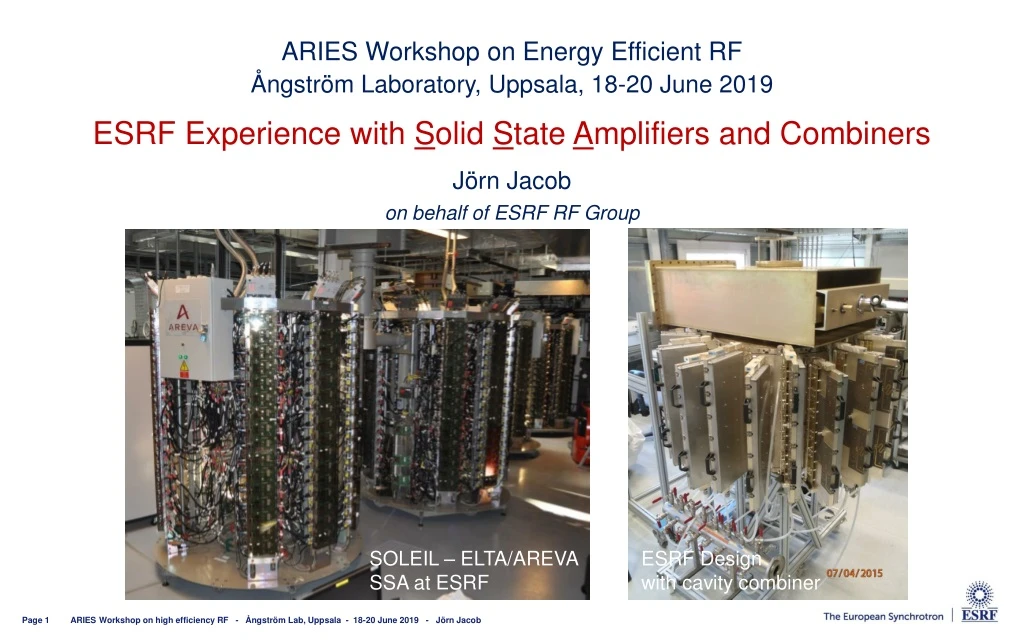
ARIES Workshop on Energy Efficient RF • ÅngströmLaboratory, Uppsala, 18-20 June 2019 • ESRF Experience with Solid State Amplifiers and Combiners Jörn Jacob on behalf of ESRF RF Group SOLEIL – ELTA/AREVA SSA at ESRF ESRF Design with cavity combiner ARIES Workshop on high efficiency RF - Ångström Lab, Uppsala - 18-20 June 2019 - Jörn Jacob
ESRF: First 3rd generation, becomes4th generation light source Up to 100 keV X-rays Circ = 844 m 6 GeV Booster 200 MeV Linac 6 GeV Storage Ring 200 mA • Existing Storage Ring • 1992: commissioning • 1994: external users • since then: • many upgrades • brilliance increase by about a factor 1000 New Extremely Brilliant Source: EBS Further brilliance increase by a factor 100 2019: installation well advanced, start up in Dec. 2020: commissioning and resume user service ARIES Workshop on high efficiency RF - Ångström Lab, Uppsala - 18-20 June 2019 - Jörn Jacob
Klys3 Klys1 Klys2 RF Layout until December 2018 6 GeV Storage Ring Cell 5 Cell 7 6 GeV Booster Teststand • 4 x 150 kW SSA [ELTA/SOLEIL] • in operation since April 2012 150 kW 150 kW pulsed SY Cav 1 & 2 150 kW • 3 x 150 kW SSA [ELTA/SOLEIL] • in operation since 2013 150 kW 150 kW • 3 prototype HOM damped cavities • In operation since 2013 • One cavity removed due to a micro leak 150 kW 5-cell cavities: strong HOM 150 kW ID ID Cell 25 ARIES Workshop on high efficiency RF - Ångström Lab, Uppsala - 18-20 June 2019 - Jörn Jacob Cell 23
EBS RF system Layout – Start up December 2019 Cell 5 Cell 7 EBS Storage Ring • Symmetric 3dB splitting using existing magic T’s -7 dB -7 dB KLYS 1 NEW RF power Teststand KLYS 2 3x existing 150 kW SSAs Space for 3rd or 4th harmonic RF system • Still under study: 5 to 7 active (?) NC cavities or passive Super3HC type • 40 kW per NC cavity from SSA Cell 25 ARIES Workshop on high efficiency RF - Ångström Lab, Uppsala - 18-20 June 2019 - Jörn Jacob 75 kW tower 75 kW tower 75 kW tower 75 kW tower 75 kW tower 75 kW tower
150 kW – 352 MHzSSAat ESRF • Pair of transistors in push-pull • (BLF578 from NXP, now produced by Ampleon) x 128 x 2 75 kW coaxial power combiner tree 150 kW - 352.2 MHz SSA DC to RF: = 58 %, G = 63.3 dB at Pnom 7 such SSAs in operation at the ESRF! • 650 W RF module • DC to RF: = 68 to 70 % • Tolerates failures: no trip even at maximum power with up to 6 faulty modules • High redundancy • Initially developed by SOLEIL • Transfer of technology to ELTA / AREVA • RF modules & coaxial lines built by BBEF (PRC) ARIES Workshop on high efficiency RF - Ångström Lab, Uppsala - 18-20 June 2019 - Jörn Jacob
AC/DC Converter 460kVA / 280VDC COMPARISIONSSA versusklystron in operation What we compare RF 352MHz Power Amplifier Lo Low Level RF HVPS 100kV Driver RF 100W Load 2 Focusing Power Supplies 2 X 130V/8A IP Power Supply 95kV/18A 5kV Power OUT Filament 25V/25A Power IN CIRCULATOR ARIES Workshop on high efficiency RF - Ångström Lab, Uppsala - 18-20 June 2019 - Jörn Jacob 1.3 MW KLYSTRON Modulating Anode 60kV/2mA ELTA/SOLEIL Solid State Amplifier
SSA versus klystron – TRIP RATE Including auxiliaries and Power supplies KLYSTRON average failure: 4 trips / year SSA average failure: 0.9 trips/ year * * When a klystron begins to be sick it can generate several beam interruptions in a short time lapse 0.5 year ARIES Workshop on high efficiency RF - Ångström Lab, Uppsala - 18-20 June 2019 - Jörn Jacob
Operation experience with 7 x 150 kW SSA • Booster 4 x 150 kW SSA, since January 2012 (6,400 hr), Top-up since April 2016 • SR 3 x150 kW SSA, since October 2013 (32,000 hr),1 stopped after a few months due to cavity • So far not a single transistor failure ! • Nominal Power Efficiency DCRF: 58%, Gain 63.3 dB – No variation in time detected so far ARIES Workshop on high efficiency RF - Ångström Lab, Uppsala - 18-20 June 2019 - Jörn Jacob
SSA : 650 W - HPA Failures Average 5 HPA failures per year for a total of 1820 HPA (128+2 / tower) ARIES Workshop on high efficiency RF - Ångström Lab, Uppsala - 18-20 June 2019 - Jörn Jacob
ELTA/SOLEIL SSA TEsts- OVERDRIVE • Avoid overdrive conditions • High peak drain voltage can damage the transistor [according to NXP] • Explains gain and efficiency degradation observed on first 75 kW tower under test at the ESRF, according to ELTA *) • Taken into account by ELTA for the fabrication of the 2nd batch of 3 x 150 kW SSA for the ESRF storage ring: • No degradation observed after 3500 hours of fatigue test with 8 amplifier modules at maximum power *) • Paid with 1 to 2 % less efficiency of the RF modules and about 1 % less efficiency at nominal power for a complete SSA • Short pulses (20 ms) • Transient gain increase up to 1.3 dB • Risk of overdrive • Overdrive protection needs to be adjusted carefully * [J.-P. Abadie & A. Cauhepe, ELTA / AREVA] ARIES Workshop on high efficiency RF - Ångström Lab, Uppsala - 18-20 June 2019 - Jörn Jacob
ELTA/SOLEIL SSA TEsts– gain modulation for mismatched load Measurement with constant RF input power level, giving 150 kW on matched load: • ± 20 kW on FwPw, i.e. gain modulation • Partially intrinsic to non directive coaxial combiner tree (confirmed by simulation) • Partially due to imperfect circulators on RF modules: modulation of load impedance RF module gain modulation Test results: • Reflected power well absorbed by circulator loads on RF modules • Despite one circulator per RF module: gain modulation • for some phases: SWR=3.7 test limited to 140 kW and short circuit test limited to 60 kW by overdrive protection Specification: • SWR = 3.7 Prefl / Pfwd = 50 kW / 150 kW, all phases ( EH – tuner) • Full reflection at all phases specified and tested for 80 kW (movable short circuit) ARIES Workshop on high efficiency RF - Ångström Lab, Uppsala - 18-20 June 2019 - Jörn Jacob
ELTA/SOLEIL SSA TEsts– overload of unpowered RF modules • SWR = 3.7 (Spec) Prefl / Pfwd = 50 kW / 150 kW, all phases ( EH – tuner) • Operation with up to 6 unpowered modules (redundancy in case of defect) • But: overpower on circulator load depending on phase of mismatch: up to 1700 W 170 mm Adjusting the length of the 2nd stage in the combiner tree by +170 mm Limit of peak reverse power to 1200 W = capacity of circulator load ARIES Workshop on high efficiency RF - ÅngströmLab, Uppsala - 18-20 June 2019 - Jörn Jacob
Transient Reflections for pulsedcavityconditioning Measurement: P = |amplitude|2 HOM damped cavity at fres R/Q = 145 Qo = 32500 = 3.8 Computation: amplitude |r| = 1.5 Incident wave amplitude Reflected wave amplitude Amplitude [a.u.] Filtered reflection signal [RC=10s] t [s] • ESRF SSPA from ELTA tested with 20 s /150 kW pulses at full reflection (spec) • Fast interlock for Prefl > 150 kW • Interlock on low pass filtered signal for Prefl > 50 kW (spec) ARIES Workshop on high efficiency RF - Ångström Lab, Uppsala - 18-20 June 2019 - Jörn Jacob
RF amplifier module: ESRF in house development Motorola patent unbalanced ESRF fully planer design: • Printed circuit baluns • RF drain chokes replaced with “quarter wave” transmission lines. • Very few components left, all of them SMD and prone to automated manufacturing • Reduced fabrication costs balanced [M. Langlois, ESRF] ARIES Workshop on high efficiency RF - Ångström Lab, Uppsala - 18-20 June 2019 - Jörn Jacob
Wilkinsonsplitterfor the RF drive distribution 50 R = 50 50 50 R = 50 3 x splitter: Length = /4 Z = 3 x 50 R = 50 50 Resistors absorb differential signals without perturbing the common mode, thereby decoupling the connected outputs from each other 50 Vdc distribution RF splitters Water cooled wing with 6 RF modules, developed at ESRF [M. Langlois, ESRF] ARIES Workshop on high efficiency RF - Ångström Lab, Uppsala - 18-20 June 2019 - Jörn Jacob
ESRF design using a cavity combiner * For 352.2 MHz ESRF application: • 6 rows x 22 Columns x 700 W per transistor module • 85 kWnominal • More compact than coaxial combiners ßwaveguidenmodule x ßmodule >> 1 • Easy to tune if nmodule is varied • Substantial reduction of losses higher h H field Homogenous magnetic coupling of all input loops E field Strong capacitive coupling to the output waveguide Strongly loaded E010 resonance • Modest field strength • Cavity at atmospheric pressure • 1 dB - Bandwidth 0.5 … 1 MHz * Received funding from the EU as work package WP7 of the FP7/ ESRFI/CRISP project ARIES Workshop on high efficiency RF - Ångström Lab, Uppsala - 18-20 June 2019 - Jörn Jacob
ESRF design using a cavity combiner • Direct coupling of RF modules to the cavity combiner: • No coaxial RF power line • Very few, sound connections • 6 RF modules are supported by a water cooled “wing” • The end plate of the wing is part of the cavity wall with built on coupling loops • One collective shielding per wing • Less than half the size of a 75 kW tower with coaxial combiner tree • RF/DC = 62 % at Pnom = 85 kW • Ptest = 90 kW • Pnom obtained with 1 wing off [M. Langlois, ESRF] ARIES Workshop on high efficiency RF - Ångström Lab, Uppsala - 18-20 June 2019 - Jörn Jacob
DC power requirement for ESRF 150 kW SSPA from ELTA 90 % ! diff = dPrf/dPdc Pdc = Prf/Pdc • 400 Vac / 280 Vdc - 360 kW Power Converters ARIES Workshop on high efficiency RF - Ångström Lab, Uppsala - 18-20 June 2019 - Jörn Jacob
DC supply of 4x 150 kW SSPA on ESRF booster Peak DC power 1000…1200 kW Average power consumption Constant AC power 300…400 kW • 4 Hz 600 kW RF Mains 400 Vac 280 V dc 280 VdcSupply 400 kW average Anti-flicker C = 4.4 F 4 SSPA incl. 280V / 50V dc/dc converter boards 4 booster cavities • Single 280 V dc / 400 kW PS for the 4 SSPA of the ESRF booster and one back up 360 kW PS • Three 280 V dc / 360 kW PS: for the 3 SR SSPA ARIES Workshop on high efficiency RF - Ångström Lab, Uppsala - 18-20 June 2019 - Jörn Jacob Capacitor cabinets
DC supplies with increased efficiency, modularity and redundancy • ESRF 352 MHz - 85 kW SSPA: • Direct 400 Vac / 50 Vdcconvertersfrom EEI • Higherefficiencythan 2 stages • OK for CW, but antiflicker capacitances for pulsedoperation 6x higherat 50 Vdc • One 160 A / 8 kW PS per wing = 6 RF modules • Redundancy:cantolerate 1 PS failureatPnomwithouttripping the SSPA • Recent SOLEIL developments: • Highly efficient ( = 96 %), modular2 kW - 240 Vac / 50 Vdcconverters, feeding 50 Vdc busses • High redundancy, toleratesconverterfailures • Remote voltage control: allowsoptimising SSPA efficiency for large range of output power: • RF/AC= 56 % atPmaxand 50 % at ½ Pmax • Architecture changedfromtower to cabinet • Example: • 500 MHz -80 kW SSPA at SESAME: • 1st one built by SOLEIL • 2nd- 4thunder SOLEIL licence by SigmaphiElectronics [P. Marchand, SOLEIL] ARIES Workshop on high efficiency RF - Ångström Lab, Uppsala - 18-20 June 2019 - Jörn Jacob
Thank you !!! ARIES Workshop on high efficiency RF - Ångström Lab, Uppsala - 18-20 June 2019 - Jörn Jacob


