Download
1 / 24
260 likes | 591 Views
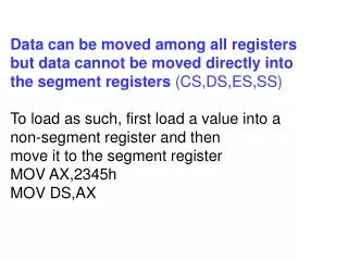
ECM534 Advanced Computer Architecture. Lecture 4. Miscellaneous Addressing Mode, Memory Map, Pointer, and ASCII. Prof. Taeweon Suh Computer Science Education Korea University. Addressing Modes.

E N D
ECM534 Advanced Computer Architecture Lecture 4. Miscellaneous Addressing Mode, Memory Map, Pointer, and ASCII Prof. Taeweon Suh Computer Science Education Korea University
Addressing Modes • The addressing mode defines how machine language instructions identify the operand(s) of each instruction • An addressing mode typically specifies how to calculate the memory address of an operand by using information held in registers and/or constants contained within a machine instruction • It is one aspect of ISA in CPU • Addressing modes in MIPS • Register-only • Immediate • Base Addressing • PC-Relative • Pseudo Direct
MIPS Addressing Modes • Register-only Addressing • R-type instructions use the register-only addressing • Operands are found in registers add $s0, $t2, $t3 sub $t8, $s1, $0 • Immediate Addressing • Some I-type instructions use the immediate addressing • 16-bit immediate is used as an operand addi $s4, $t5, -73 ori $t3, $t7, 0xFF
MIPS Addressing Modes • Base Addressing • The address of the memory is found by adding the base address (rs) to the sign-extended 16-bit offset (imm) • Address calculation of an operand base address + sign-extended immediate lw $s4, 72($0)// address = $0 + 72 sw $t2, -25($t1) // address = $t1 - 25
MIPS Addressing Modes • PC-Relative Addressing • Conditional branch instructions use PC-relative addressing to specify the new PC if the branch is taken • The signed offset in the immediate field is added to the PC to obtain the new PC • Thus, the branch destination address is said to be relative to the current PC 0x10 beq $t0, $0, else 0x14 addi $v0, $0, 1 0x18 addi $sp, $sp, i 0x1C jr $ra 0x20 else: addi $a0, $a0, -1 0x24 jal factorial
MIPS Addressing Modes • Pseudo-direct Addressing • In direct addressing, an address is specified in the instruction • But, the J-type instruction encoding does not have enough bits to specify a full 32-bit jump address • Opcode uses the 6 bits of the instructions • So, only 26-bits are left to encode the jump target address • MIPS calculates the jump target address from the J-type instruction by appending two 0’s and prepending the four MSBs of PC + 4 destination = {(PC+4)[31:28] , jump target, 2’b00}
ASCII Encoding • In old days, exchanging text between computers was difficult because early computers lacked a standard mapping between bytes and characters • In 1963, the American Standards Association published the American Standard Code for Information Interchange (ASCII) • ASCII assigns each text character a unique byte value • C language uses the type char to represent a character
Example #include <stdio.h> int main() { char aa, bb; char * addr_aa; char * addr_bb; aa = 'A'; bb = 'a'; addr_aa = &aa ; addr_bb = &bb ; printf("%c is stored as h'%x in memory\n", aa, *addr_aa); printf("%c is stored as h'%x in memory\n", bb, *addr_bb); }
Arrays • Arrays are useful for accessing large amounts of similar data • Array element is accessed by index • Array size is the number of elements in the array • Example • 5-element array of integer (int table[5];) • Base address = 0x12348000 (address of the first array element, table[0]) • First step in accessing an array: load base address into a register int a ; a = *(table + 3) Main memory 0x1234_8010 table + 4 table[4] 0x1234_800C table + 3 table[3] compile // $s0 = base address of the array // $t0 = a lw $t0, 12($s0); 0x1234_8008 table[2] table + 2 0x1234_8004 table[1] table + 1 table[0] 0x1234_8000 table = &table[0]
Arrays vs Pointers • Array indexing involves • Multiplying index by element size • Adding to array base address • Pointers correspond directly to memory addresses &array[0] &array[0]
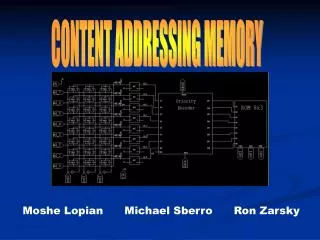
Memory Map • Memory map indicates how memory space is laid out • Where the main memory and I/O devices are located in the memory space • Memory-mapped I/Os: when I/O devices are mapped in memory space, they are said to be memory-mapped I/Os • Memory space is determined based on the size of the address bus • If the address bus is 32-bit wide, memory space is 4GB • If the address bus is 48-bit wide, memory space is 256TB CPU Main Memory (DDR) FSB (Front-Side Bus) 0xFFFF_FFFF Memory Space North Bridge BIOS ROM 0xE000_0000 DMI (Direct Media I/F) 0x7FFF_FFFF Memory in Graphics card South Bridge 0x7000_0000 0x3FFF_FFFF Main memory (1GB) Byte address 0x00000000
Our Computer System for Project • We are going to use a simple computer system consisting of MIPS (not a complete MIPS), memory, and 2 peripheral devices (Timer and GPIO) • GPIO stands for General-Purpose I/O • Virtually all the peripheral devices have registers inside, so they can be programmed by software
Our Computer System Instruction Data MIPS CPU Address Bus Address Bus EAX R31 …. ALU R1 R0 Timer 32-bit 32-bit GPIO 8KB Memory (Instructions, Data) 32-bit 32-bit Data Bus Data Bus
Our Computer System in FPGA MIPS CPU Address Bus Address Bus EAX R15 …. ALU R1 R0 Timer 32-bit GPIO 32-bit 8KB Memory 32-bit 32-bit Data Bus Data Bus
7 Segments and LEDs Connection MIPS CPU Address Bus Address Bus EAX R15 ALU …. R1 R0 Timer 32-bit GPIO 32-bit 8KB Memory 32-bit 32-bit … 7 segments and LEDs Data Bus Data Bus
Memory Map of Our System • Memory map of our system • You can change the map if you want by editing Addr_decoder.v Address Bus 0xFFFF_FFFF Memory Space 0xFFFF_3000 MIPS CPU 4KB GPIO 0xFFFF_2000 EAX R31 0xFFFF_1000 …. ALU 32-bit Timer 4KB R1 0xFFFF_0000 R0 32-bit 0x0000_2000 0x0000_1FFF 8KB Memory Data Bus 8KB 0x0
Linker Script • Check out the linker script in Makefile • Figure out what the linker script says where the code and data in the program should be located in memory testvec.s .text .align 4 la $sp, stack # load address j SevenSeg .data .align 4 stack: .space 1024 testvec.lds SECTIONS { . = 0x00000000; .text : { *(.text) *(.rodata) } . = ALIGN(1024); .data : {*(.data)} .bss : {*(.bss)} }
The MIPS Memory Map • Addresses shown are only a software convention (not part of the MIPS architecture) • Text segment: Instructions are located here • The size is almost 256MB • Static and global data segment for constants and other static variables • In contrast to local variables, global variables can be seen by all procedures in a program • Global variables are declared outside the main in C • The size of the global data segment is 64KB • Dynamic data segment holds stack and heap • Data in this segment are dynamically allocated and deallocated throughout the execution of the program • Stack is used • To save and restore registers used by procedures • To hold local variables • Heap stores data that is allocated by the program during runtime • Allocate space on the heap with malloc() and free it with free() in C • Reserved segments are used by the operating system
Example Program int f, g, y; // global variables int main(void) { f = 2; // g = 3; // y = sum(f, g); return y; } int sum(int a, int b) { return (a + b); } .data f: g: y: .text main: addi $sp, $sp, -4 # stack frame sw $ra, 0($sp) # store $ra addi $a0, $0, 2 # $a0 = 2 sw $a0, f # f = 2 addi $a1, $0, 3 # $a1 = 3 sw $a1, g # g = 3 jal sum # call sum sw $v0, y # y = sum() lw $ra, 0($sp) # restore $ra addi $sp, $sp, 4 # restore $sp jr $ra # return to OS sum: add $v0, $a0, $a1 # $v0 = a + b jr $ra # return compile
Symbol Table of Example Program • Assembler creates a symbol table that contains the names and their corresponding addresses of symbols (such as labels and global variable names)