Download
1 / 65

E N D
PREPARED BY ©right Name : MAZADUL HASAN SHESHIR ID: 2010000400008 Batch: 13th Batch (Session 2009-2013) Department: Wet Processing Technology Email: mazadulhasan@yahoo.com Blog: www. Textilelab.blogspot.com Southeast University Department of Textile Engineering
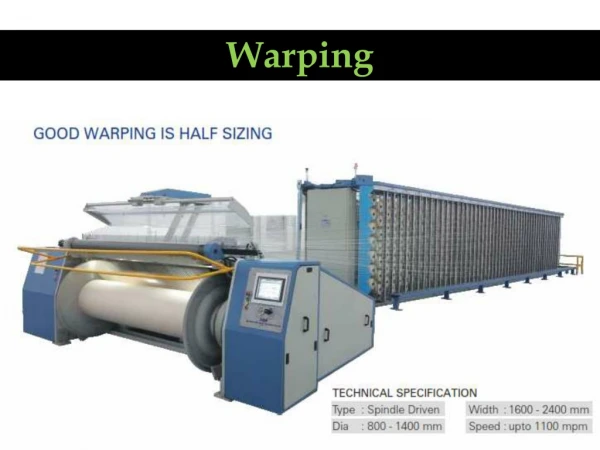
WARPING: Warping: The parallel winding of warp ends from many winding packages (cone or cheese) on to a common package (warp beam) is called warping. Types of warping: 1. Beam warping – direct warping. 2. Patterns band or drum warping – Sectioned warping,(Indirect warping) 3. Ball warping
TYPES OF WARPING Direct Warping Denotes the transference of yarns from single-end yarn packages, wound packages, directly to a beam in a one step process. This means that there are an equal number of packages in the creel area as there are ends on the beam, except in the case of a magazine creel. A magazine creel connects the tail of one wound package to the beginning of a new wound package for an easy package transfer. from the wound packages in the creel. Beam Warping A weavers beam may have upto 10,000 ends and if this were to be produced directly it would be necessary to have upto 10,000 creel packages.such an arrangement would be very difficult to accommodate and manage ;consequently it is normal practice to produce warpers beams which may contain upto about 1000 ends and these are combined at the slashing stage.because of the difficulties involved in combining the ends ,patterned warper beams are seldom produced on the direct system and any pattern that is produced is achieved by combining beams of various colors at the later stage of slashing. This imposes limitations which can only overcome by changing to pattern weaving.
TYPES OF WARPING Sectional Warping Process In sectional warping sections are made sequentially and because of this the process is rather slow ;it is the practice therefore to produce no more than is required to fill a single weavers beam.the result is that the sectional warping is used mainly for short runs or for complex color patterns. Pattern, Band or Drum Warping Because many warpers beams are combined in the direct system,this is usually regarded as a high speed process particularly suitable for single color work .providing the warpers beams are of single color ,it is possible to combine them to produce simple patterns distributed over the warp width. Ball warping Ball Warping is an intermediate process for storing yarn for transport ,dyeing or reserve; It does not produce a beam.the usual form is a cross wound cheese in which multiple ends are wound at the same time in a ribbon which contains perhaps 50 or 100 ends.
QUALITY OF A GOOD WARP The essential features of a good warp are as follows: 1. Sufficiently and uniformly strong 2. Uniform in cross section 3. Uniform warp tension 4. Uniformly sized 5. Less hairy and clean 6. Minimum no of knots 7. Proper or standard size and types of knots 8. Free from neps, slubs and loose fibres 9. Parallel arrangement of warp yarn in the weavers beam
WARPING ELEMENTS & MOTION Each warping m/c has the following warping elements & motion: 1. Warping creel for accommodation the bobbin. 2. A builder motion. 3. A guide reed. Uniformly spreading the yarn over the warp width. 4. A measuring motion registering the warping length. 5. An automatic knocking off motion to stop the m/c up on achieving the required length of warping in case of yarn breakage. 6. A drive 7. A starting & stopping motion. 8. Warping m/c is furnished with package doffers signal devices, blowers. Fluff -exhaust system.
REQUIREMENT OF WARPING Should meet the following requirement: 1. The tension of all wound ends must be uniform and possibly constant during all the time of withdrawal from supply packages, otherwise the rate of breakage will be increased & the structure of the ready cloth will be impaired. 2. Warping should not impair the physical & mechanical properties of yarn. The tension should moderate to allow the yarn to completely retain its elastic properties & strength. The yarn should not be subjected to sharp abrasive action. 3. The surface of warping package must be cylindrical. Therefore, the spreading of yarn (density) throughout the whole width of warping must be as uniform as possible. 4. A pre determined length of warping should be observed. 5. The production rate of warping should be as high as possible.
REQUIREMENT OF WARPING 1. The yarns in the sheet should be in uniform spacing. 2. The yarns in the sheet should be in uniform tension. 3. The yarns in the sheet should be of a predetermined length. 4. The sheet should be containing a predetermined number of ends. 5. There should be no broken ends in the beam.
OBJECTS OF WARPING Objects of warping: The object of warping is to convert a predetermined number of single end packages, such as cones or cheeses into a sheet of yarn of specified length & width. The individual’s ends in the warp are uniformly spaced across its full width. The warp yarns comprise one of the systems of yarns required to produce a woven fabric & also for warp knitting. The objective at warping, as erroneously considered by many is not at all to remove yarn faults, the breaks due to these being only incidental.
CHECK LIST BEFORE PRODUCTION Check List Before Production: 1. With the production before data control operator will call-up the following for recording: 2. Warp length shift 3. Down time. 4. Efficiency. 5. No. of thread breaks. 6. No. of warp beam doffed. 7. Time for thread repair. 8. Time for beam change. 9. Operator must check yarn quality in term of count, material, and color with customer demand. No mixing is allowed. 10.Operator must check yarn quality in term of strength and record yarn break rate. Standard for good quality yarn 10 breaks/1000000 meter.
IMPORTANCE OF WARPING Importance of warping: 1. Constructions of beam warp yarn. 2. Constructions of a parallel yarn sheet. 3. Modifying the faults of yarn like thick & thin places, large knots etc. 4. Winding the predetermined length of yarn. 5. Combination of small packages. 6. Finding long length of warp yarn. 7. Accelerating the next process.
PRODUCT QUALITY CHECK QUALITY PARAMETER CHECK RESPONSE No ridge beam allowed, clean the yarn Beam surface smoothness guide & check the tension for uniformity. Check the alignment of beam & drum, drum Homogeneous beam diameter and creel etc. Yarn exhaustion Replace exhaustion cone with new one. Tying the head end with tail end with Yarn break standard with fail size <3 mm.
Operational Stuff Operational Staff: Section in – Charge Senior Executive ↓ Quality Control Officer ↓ Supervising officer ↓ Senior Operator ↓ Creel man ↓ Helper Operational Stuff: 1. SUPERVISING OFFICER. 2. OPERATOR. 3. CREEL MAN. 4. HELPER.
OPERATION PROCEDURE: As per production program given by Assistant Manager, preparation through the yarn. Warped Record Register; the Supervising Officer collect greige yarn from the store as per required count Lot no. & quality. The m/c operators and helpers and helpers open/break the yarn cartons & place the yarn cones on the creel peg as per program & draw the head end of each cone through pre-tensioner rods feeler wire, yarn guide & then through expanded comb of beaming unit. The basic creel data setting& m/c data setting are done according for the required as pr m/c manufacturer instruction. An empty beam is set between driving clutch & engaged by means of electric switch. All the ends from the creel is warped around the beam manually one round. The press roller is moved toward the beam by means of electric switch.
OPERATION PROCEDURE: The m/c is then run slowly and checked for yarn alignment with beam flange on both sides. To ensure perfect alignment the expended comb may be moved either to the Right side or Left side as required by switch. Then the m/c is ready & operational & the switch is to be turned on. As the present length is achieved the m/c will stop automatically. The beam is doffed by switch. Another empty beam is mounted. In this way a set of beam are made to feed the subsequent sizing process. Production is recorded in the yarn Warped Record Register. Each beam is set with warping Data sticker for identification in the next process.
WARPING PROCEDURE 1. Based on weave plan supervising officer and/or senior operator receive the required dyed yarn from winding section of specific customer order no. as per color and quantity. 2. As per worked out warp pattern scheme senior operator arrange the yarns on the creel following the color pattern. Quality control officer will check any shade variation within the same color. If any variation is found, necessary steps should be taken to use them lot by lot. Quality control officer will sign on the warping program register. 3. The operator & creel man draw the yarn through feeler wire on creel & splits of the leasing reed & then through guide reed & tie in. 4. Then the main switch of main control panel is turned on & cone alignment is done by respective switch. 5. Senior operator will put necessary data entry on the warping data sheet by taking some figure from yarn warped record register & by calculating some values as per prescribed formula in the m/c manufacturers operating instruction book. He will also input these required figurers in the control data unit of the m/c.
WARPING PROCEDURE 6. Hook warp section on to the drum by opening & closing the guide roller. 7. Start warping by pressing foot pedal at the head stock. Machine will run slowly at crawl speed. After 15 meter being wound on, stop the m/c and insert leasing threads. Then again start m/c with run switch at the head stock and finish warping of the section. 8. Then by section alignment switch set the m/c ready for next section. Repeat step-7, and 8 to finish the warping.
WARPING PROCEDURE All the section thatare wounded up over the drum is doffed in the beam from by beaming process as follows: Turn the switch from warping to beaming. Set an empty beam in the beam during unit by beam barrel by an adhesive tape and rotate the beam manually. Set beam flange with measured warp width. Set winding tension value range from 1-6 (calculated value as attached). Run at crawl speed to see alignment either left side or right side by drum alignment switch. Set the winding speed within a range of 1-160 m/min, depending on yarn quality. Run the m/c with run switch. Doff the beam by unloading switch. Warping data sheet is failed as a production record. Each beam is set with a warping data sticker for identification in the next process.
YARN PATH DIAGRAM OF HI-SPEED WARPING MACHINE Main Parts: 1. Yarn cone or Chase 2. Balloon Breaker 3. Yarn tensioner 4. Yarn guide 5. Ceramic guide 6. Auto stopper 7. V-reed 8. Lease rod 9. Roller 10. Pressure Roller 11. Pre-beam
PROCESS FLOW CHART HI-SPEED WARPING MACHINE Dispo ↓ Yarn from store ↓ Creeling ↓ Warping
COMPONENTS OF WARPING MACHINE CREEL: 1. 2. 3. 4. 5. 6. ConeHolder Yarn Guide Tension Rod Ceramic Guide Disc Auto Stop Sensor Creel Panel Board : Hold the cone or arrange the cone in the creel. : To guide the yarn. : Maintain yarn tension by upper & lower disc tensioner. : To guide the yarn from creel to warping m/c. : To sense the breakage yarn. : Display where the yarn break. HEAD STOCK: 1. Guide Reed 2. Adjustable V-Reed 3. Speed Controller 4. Pressure Roller 5. Measuring Device 6. Beam Bracket 7. Emergency Stop Device: For emergency stop. 8. Automatic Knock Off 9. Yarn breaks. 10. Electrical Panel Board : To give the automatic controlled function. : Uniformly spread the yarn over the warp width. : Guides the yarn to follow the fixed path. : control the speed, crawl speed or full speed. : Exert required pressure to the warp yarn. : Measures the length of the yarn. : Holds the warp beam. : Stop m/c at achieving required length of beam or in case of
Major components of Warping Machine: Warping machine has three major components: 1. Creel 2. Head Stock 3. Control Device Creel: •Parallel creel with travelling package •Creel capacity of SIM fabric direct warping m/c: oNo. of warping m/c: 2 oM/c no 1: Both side: 756
FUNCTION OF COMPONENTS OF CREEL Function of components of creel: 1. Cone or cheese spindle for high speed warping. 2. Thread guide: To pass through the yarn in the reqd way. 3. Tensioner: To keep the yarn always in a uniform tension. 4. Yarn cleaner: To remove various faults of yarn like slubs, neps etc. 5. Suction fan or blower: To remove the dirt & dust from the yarn. 6. Breakage indicator: To indicate breakage in package. 7. Stop device: To stop the m/c when yarn will be broken.
HEAD STOCK Features of components of headstock: 1. Adjustable or variable v-reed or wraith: To control the width of the warp beam. 2. Measuring & making device: Measure the amount of warp yarn on the beam & marks the yarn. 3. Yarn speed controlling device: To control the speed of yarn. 4. Pneumatic pressure unit: To press the warp beam with the surface contact of driving drum. 5. Break assembly: It stop the m/c after read length is wound on beam. 6. Driving drum: Beam is in contact & control with driving drum. 7. Stop motion: Used to stop the m/c after read length is wound on beam. 8. Beam bracket: To support & hold the beam. 9. Lease rod: Used for separation of yarn individually.
Control device: Similar to winding, warp yarns are threaded through tension devices , stop motions, leasing rods and the reed. The stop motion electrically links each warp end to the warper braking system; when a warp end breaks, the warper stops. A light indicates the location of the broken end. The warping process is generally irreversible, unwinding, of the beam would cause yarn entanglement. The stop motion device which can be mechanical or electronic for quick response, is usually located near the creel.Fans are used to prevent lint accumulation when warping staple yarns.
# Pressure setting of stop motion & tensioner: (Off Creel) Setting is adjustable by rotary button, which activate stop motion drop wire & pressure. Stop motion Tension Setting range Yarn Count (Ne) 3 C Coarse 4-30S 2 B` Medium 4-60S 1 A Fine 15-120s
High Speed Warping m/c Setting: Set up parameters Range Set value Cone no. of Creel 400-600 As required Warping Speed 1-1200 m/min Warping length 1-999999 m Shift selection 1-5 3 Beaming drum pressure 1-11 mm scale 5 mm scale Stop drop wire 1, 2, 3. 1 higher Tensioner A, B, C. C higher Depth of penetration 1-40 mm As required Beam barrel dia 315 mm Fixed Beam flange dia. 987 mm Fixed Beam width 1800 mm As required
DIFFERENCE BETWEEN DIRECT & SECTIONAL WARPING PARAMETERS DIRECT WARPING It is generally used to produce warp beam for grey fabric or solid color fabric. SECTIONAL WARPING It is generally used to produce warp beam for yarn dyed (check/stripe) fabric. Object / Use Several Warpers beam are produced here for getting one weavers´ beam. One Warpers beam is produced here for getting one weavers´ beam. Method of production Ends/beam is less here. Direct warping beams contain 1/n no. of ends of weavers´ beam. (n=no. of warping beam/set). Ends/beam is higher here. Sectional warping beam contains equal no. of ends as weavers´ beam. No. of Ends/beam One stage Production.(Yarns are directly wound on Warpers´ beam). Two stage Production. (Yarns are directly wound on warping drum section by section; then the sheet is transferred to warpers´beam). Stage of Production
DIFFERENCE BETWEEN DIRECT & SECTIONAL WARPING PARAMETERS DIRECT WARPING Yarn tension is comparatively higher than sectional warping. Higher length of yarn is wound on a beam. SECTIONAL WARPING Yarn tension is comparatively lower than sectional warping. Length of yarn in the beam is comparatively lower than direct warping. Usually higher than sectional warping. One sized beam is produced from one Warpers´ beam. Yarn Tension Yarn length on beam Usually lower than sectional warping. One sized beam is produced from several no. of Warpers´ beam. Efficiency is higher than sectional warping. (Single stage operation). Creel Capacity Sizing Operation Efficiency is comparatively lower than direct warping. (One additional operation beaming-off is required). Efficiency
Process Flow Chart Sectional Warping Machine Process Flow: Dispo ↓ Yarn from store ↓ Creeling (According to warp plan) ↓ Machine setup ↓ Section wise warping ↓ Beaming Warp width: Total Ends Warp Width Below 7200 1800 mm 7200 2000 mm Above 7200 2100 mm
Control Data Parameter Evaluation: 0.5 Ends Decitex Total Feed- 1 = Warp Density Total width Feed 2= Measured feed X 0.85 ( For Cotton) = Measured feed X 0.95 (For Synthetic) Feed -1= Drum Movement with revolution per minute. Feed -2= Actual movement of Drum. Measured feed=> It find out the variation between Feed -1 to Feed -2 Variation +/- 15% Piece length= Machine stop before wound 10 -15 meter of required length.
Ball warping Machine In ball warping process, individual strands of yarn are removed from yarn packages and collected into rope form suitable for rope dyeing (Fig. 2). Threads, about 350-500 in number are formed into ropes. Individual warp yarn are collected into rope form and wound onto a log and produce a ball warp on Ball warping machine. In ball warping, all the packages are loaded into the adapters of the creel of ball warping machine. The creel is normally designed to accommodate about 330 to 430 packages. The creel may be of different types, such as Magazine Creels and Traveling Package Creels. The passage of yarn in ball warping are shown in Fig..