Download
1 / 42
510 likes | 1.76k Views
High Voltage Engineering For Modern Transmission Networks. Michael MUHR O.Univ.-Prof. Dipl.-Ing. Dr.techn. Dr.h.c. Institute for High-Voltage Engineering and Systems Management Graz University of Technology Austria. Content. 1. Introduction 2. High Voltage AC Transmission (HVAC)

E N D
High Voltage Engineering For Modern Transmission Networks Michael MUHR O.Univ.-Prof. Dipl.-Ing. Dr.techn. Dr.h.c. Institute for High-Voltage Engineering and Systems Management Graz University of Technology Austria
Content 1. Introduction 2. High Voltage AC Transmission (HVAC) 3. High Voltage DC Transmission (HVDC) 4. Future Developments & Trends 5. Transmission Lines 6. Overhead Lines 7. Cable Lines 8. Gas-Insulated Lines 9. Technical Developments 10. Summary
1. Introduction Essential changes in the framework: • Liberalisation of the electricity market • Increasing of electricity transportation / transit • Renewable Energies are on the rise • Maintenance and modernisation / replacement
Source: IEA; UN; Siemens PG CS4 - 08/2002 Development of the world population and the power consumption between 1980 and 2020
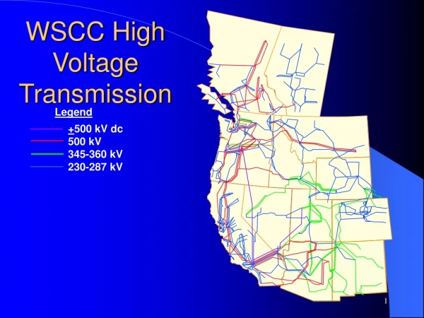
2. High Voltage AC Transmission (HVAC) • Economical environmentally friendly and low-losses only with the usage of high voltage • Voltage levels for HVAC in Austria and major parts of Europe: 110 kV, 220 kV and 380 kV • Advantage: Easy transformation of energy between the different voltage levels, convenient and safe handling (application) • Unfavourable: Transmission and compensation of reactive power, stability problems, frequency effects can cause voltage differences and load angle issues at long lines
In Discussion: China 1000 kV Japan 1100 kV India 1200 kV Source: SIEMENS Development of Voltage Levels for HVAC
Control of active power flow • Phase Shifter Transformer (PST) • Flexible AC Transmission Systems (FACTS) FACTS – Elements: • Elements controllable with power electronics • System is more flexible and is able to react fast to changes in the grid • Control of power flow and compensation of reactive power
~ w/o PST i1 X1 itotal i2 X2 UPST with PST i1+Δi itotal X1 i2-Δi X2 Phase shift transformers (PST) • Distribution of current depends on Impedances only • Unequal distribution Implementation of additional voltage sources • Control of active power flow • Additional voltage with 90° shift of phase voltage • PST implements a well-defined phase-shift between primary and secondary part of the transformer
3. High Voltage DC Transmission (HVDC) • Transmission of high amounts of electrical power over long lines (> 1000 km) • Sub-sea power links (submarine cables)No compensation of reactive power necessary • Coupling of grids with different network frequency • Asynchronous operation • Low couple - power
Advantages of HVDC • No (capacitive) charging currents • Grid coupling (without rise of short-circuit current) • No stability problems (frequency) • Higher power transfer • No inductive voltage drop • No Skin-Effect • High flexibility and controllability Disadvantages of HVDC • Additional costs for converter station and filters • Harmonics • requires reactive power • Expensive circuit breakers • Low overload capability
Source: SIEMENS PTD SE NC - 2002 4. Future Trends Costs of a high voltage transmission system
Alternating Current (AC) Direct Current (DC) Hybrid AC / DC - Connection Possibilities for Transmission Systems for high power Hybrid Connection Source: SIEMENS
Network Stability • Separation of large and heavy meshed networks to prevent mutual influences and stability issues • Usage of HVDC close couplings • Fast control of frequency and transfer power possible • Limitation of short-circuit power • Improvement of transient network stability
5. Transmission Lines • Liberalisation of the Electricity Market • Renewable Energy is on the rise • Increased environmental awareness • Possibilities for • Transmission Lines • in High Voltage Networks: • Overhead Line • Cable Line • Gas Insulated Line Decision Criteria
Framework • Economic necessity • Transmission capacity • Voltage level • Comply with (n-1) – criteria • Reliability of supply • Operational conditions • Environmental requirements • (Civil) engineering feasibility • Economics
6. Overhead Lines • Insulating Material: Air • High voltages are easy to handle with sufficient distances/clearances and lengths • Permitted phase wire temperature of phase wires is determined by mechanical strength • Overhead lines are defined by their natural power PNat • Thermal Power limit is a multiple of PNat
6. Overhead Lines – Advantages • Simple and straightforward layout • (Relatively) easy and fast to erect and to repair • Good operating behaviour • Long physical life • Large load capacity and overload capability • Lowest (capacitive) reactive power of all systems • Longest operational experience • Lowest unavailability • Lowest investment costs
6. Overhead Lines – Disadvantages • High failure rate (most failure are arc failures without consequences) • Impairment of landscape (visibility) • Low electromagnetic fields can be achieved through distances and arrangements • Highest losses • Highest operational costs because of current-dependent losses
7. Cable Lines • Insulating Materials • Plastics/Synthetics (PE, XLPE) • Oil – Paper • Polypropylene Laminated Paper (PPLP): reduced power loss and higher electrical strength than oil-paper cables • Synthetic cables are environmental friendly, dielectrics undergo an ageing process, voltage levels are currently limited to about 500 kV • Cables have a high capacitance large capacitive currents limits maximum (cable) line length compensation • Transferable power is limited by: • permitted temperature of the dielectric • high thermal resistances of accessories & auxiliary equipment • soil condition • Thermal Power Stherm is essential for continuous rating/operation • High voltage cables have a much higher Pnat than Stherm (of about 2...6)
7. Cable Lines – Advantages • Large load capacity possible with thermal foundation and cross-bonding • Lower impedances per unit length when compared to overhead lines • Lower failure rate than overhead lines • No electrical field on the outside • Losses are only 50% of an overhead line • Operational costs (including losses) are about half of the costs of an overhead line
7. Cable Lines - Disadvantages • High requirements to purity of synthetic insulation and water- tightness • Overload only temporary possible ð influences lifespan of insulation • High reactive power, compensation necessary • PD-Monitoring on bushings, temperature monitoring • Unavailability is notable higher when compared to overhead lines (high repairing efforts) • Lifespan: 30 to 40 years (assumed) • Extensive demand of space, drying out of soil, only very limited usage of line route possible • threshold value for the magnetic field (100 µT) can be exceeded • 3-6 times investment costs compared to overhead lines
8. Gas-Insulated Lines (GIL) • Insulating Material: SF6 and N2: Currently 80% N2 and 20 % SF6; pressure: 3 to 6 bar • Currently no buried lines; laying only in tunnels or openly • Many flanges necessary • Compensation of (axial) thermal expansion of ducts • SF6: Environmental compatibility ? • Gas monitoring • Easy conversion from other line systems to GIL • High transmission capacity • large overload capability • Minimal dielectric losses • Low mutual capacitance low charging current / power • Good heat dissipation to the environment
8. Gas-Insulated Lines – Advantages • Large transmission capacity • High load capacity • High overload capability • Lower impedance per unit length than overhead lines • Low failure rates • High lifespan expected (Experience with GIS) • No ageing • Lowest electro-magnetically fields • Lower losses than cables • Lower operational costs (including losses) than cable lines
8. Gas-Insulated Lines – Disadvantages • High Requirements to purity and gas-tightness • Higher reactive power than overhead lines • Gas monitoring, failure location, PD-monitoring • Higher unavailability than cables because of long period of repair • Short operational experience, only short distances in operation • Large sections necessary, only limited usage of soil possible, issues with SF6 • Investment costs 7-12 times higher when compared to overhead lines
9. Technical Development • High Temperature Superconductivity (HTS) • Cable Technology: New developments are applied to medium voltage networks • Reduced losses • Reduced weight • Compact systems • Temperature currently 138 K (- 135 °C)
Nanotechnology • Nanotechnology for cables for medium and high voltage applications (voltage level up to about 500 kV) • Advantages: • Reduction of space charge • Improved partial discharge behaviour • Increase of the electric field strength for the dielectric breakdown
10. Summary – Energy Transmission Energy Losses • Joule Effect – Heating of conductors • Magnetic losses – Energy in the magnetic field • Dielectric losses – Energy in the insulating materials Remedies • Transformers with reduced losses • Transformers with superconductivity • High temperature superconductivity (HTS) - Cables • Nanotechnology • Direct Current Transmission (HVDC) • Ultra High Voltage (UHV)
Transmission Systems (1) Alternating Current Transmission (HVAC) • All 3 Systems possible • Overhead lines up to 1500 kV (multiple conductor wires) • Cable lines up to 500 kV • GIL currently up to 550 kV, higher voltages possible
Transmission Systems (2) Direct Current Transmission (HVDC) • Overhead lines up to 1000 kV possible • Oil-Paper cables up to 500 kV • Cables with synthetic materials up to 200 kV (space charges), with nanotechnology higher values are possible (~ 500 kV) • GIL is currently under research
Transmission Systems (3) • In general, overhead-, cable- and gas-insulated lines are suitable for alternating current transmission systems • Cables and GIL are currently only applied for short lengths specifically for example in urban areas, tunnels, under- crossings, etc. Therefore no operational experience nor actual costs can be given for long sections • In a macro-economical point of view, overhead lines are the most favourable system (the capital value of cables 2 to 3 times and GIL 4 to 6 higher) • Currently overhead lines are from the technical and economical point of view the best solution