Download
1 / 5
50 likes | 169 Views
Revision with Reason. No. Date. Initials. B. B. A. A. Quantity. Parts List. Supplier. Drawing No. D’Vinyl Inc. Descriptive Part Name. Quantity Required. Foot Plate. 26. Drawing Type. Drawing Size. Scale as Drawn. Scale as Printed. part. A 8 x10. 1:1, 1in=1in. 1:1 =100%.

E N D
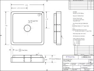
Revision with Reason No. Date Initials B B A A Quantity Parts List Supplier Drawing No. D’Vinyl Inc. Descriptive Part Name Quantity Required Foot Plate 26 Drawing Type Drawing Size Scale as Drawn Scale as Printed part A 8 x10 1:1, 1in=1in 1:1 =100% Designed by Checked by Engineer D. Quesnel D. Quesnel Drawing Issue Date Date of This Revision Engineer Phone # 02/27/99 02/27/99 275-5215 3.50 J-FRM-0101 1.75 NOTES: Suitable for CNC Milling Material: Cold Roll Steel four per frame except six for process zone frame Total 4X5+6=26 Stock Finish OK ALL SURFACES Match Radii of 3.5” Square Tube Nominal Dimension so Foot fits and centers inside 3.5” square Tube Break sharp edges and corners All dimensions in inch units. Unless otherwise indicated, use default tolerances below x.x +/- 0.050” x.xx +/- 0.010” x.xxx +/- 0.005” Angles +/- 2o 1.75 Tap Through Hole 3/4 -10 3.50 3/16 Four Sides 0.75 (stock Thickness) 0.50
Revision with Reason No. Date Initials Quantity Parts List Supplier Drawing No. D’Vinyl Inc. Descriptive Part Name Quantity Required Foot Plate Assembly 26 Drawing Type Drawing Size Scale as Drawn Scale as Printed Assembly A 8 x10 1:1, 1in=1in 1:1 =100% Designed by Checked by Engineer D. Quesnel D. Quesnel Drawing Issue Date Date of This Revision Engineer Phone # 02/27/99 02/27/99 275-5215 J-FRM-0102 NOTES: 3/16 inch 6-32 pointed set screws Set Screws Must be on exterior surface and interior surface so both set screws are accessible after frames are butted together. Centering of Set screws is visual Center Break sharp edges and corners All dimensions in inch units. Unless otherwise indicated, use default tolerances below x.x +/- 0.050” x.xx +/- 0.010” x.xxx +/- 0.005” Angles +/- 2o A View of Bottom of Frame Leg Looking in Process Direction Tap 6-32 Two Places Centered on Inside and Outside Faces A 1/8 1 each Foot Plate, J-FRM-0101 RCIMS 2 each 6-32 pointed allen set screw, 3/16 length Any Vendor 1 each 3/4 -10 Jam Nut Any Vendor 1 each 3/4 -10 1.5 inch Hex Head Cap Screw Any Vendor Jam Nut 3/4-10 Hex Head Cap Screw-Grade 5
Revision with Reason No. Date Initials A A Quantity Parts List Supplier Drawing No. D’Vinyl Inc. Descriptive Part Name Quantity Required Alignment Tab 10 Drawing Type Drawing Size Scale as Drawn Scale as Printed Part A 8 x10 1:1, 1in=1in 1:1 =100% Designed by Checked by Engineer D Quesnel D.Quesnel Drawing Issue Date Date of This Revision Engineer Phone # 3/3/99 3/3/99 275-5215 6.75 J-FRM-0103 4.25 0.44 (nominal 7/16) 2.50 1.75 0.50 Through Drill Clearance for 3/8-24 Tap for 1/4-20 +.010 -.000 2.00 0.750 1.00 Material: 1/2” Cold Rolled Steel Notes Two per framejoining 2X(6-1)=10 Holes 1.75 inch on centers Slot and Holes on Centerline Radius Nominal 1/8, 1/4” Mill Finish OK Break sharp edges and corners All dimensions in inch units. Unless otherwise indicated, use default tolerances below x.x +/- 0.050” x.xx +/- 0.010” x.xxx +/- 0.005” Angles +/- 2o
Revision with Reason No. Date Initials A A Quantity Parts List Supplier Drawing No. D’Vinyl Inc. Descriptive Part Name Quantity Required Alignment Tab Slider ### Drawing Type Drawing Size Scale as Drawn Scale as Printed Part A 8 x10 1:1, 1in=1in 1:1 =100% Designed by Checked by Engineer D. Quesnel D. Quesnel Drawing Issue Date Date of This Revision Engineer Phone # 3/3/99 2/2/99 275-5215 J-FRM-0104 Material: Cold Rolled Steel 2.375 Notes Holes 1.75 inch on centers Sliding fit into Slot in Alignment Tab Break sharp edges and corners All dimensions in inch units. Unless otherwise indicated, use default tolerances below x.x +/- 0.050” x.xx +/- 0.010” x.xxx +/- 0.005” Angles +/- 2o 0.3125 Clearance for 3/8-24, Two Places 1.750 0.75 0.375 0.50
Revision with Reason No. Date Initials Quantity Parts List Supplier Drawing No. D’Vinyl Inc. Descriptive Part Name Quantity Required Alignment Tab Assembly NA Drawing Type Drawing Size Scale as Drawn Scale as Printed Assembly A 8 x10 1:1, 1in=1in 1:1 =100% Designed by Checked by Engineer D Quesnel D. Quesnel Drawing Issue Date Date of This Revision Engineer Phone # 3/3/99 3/3/99 275-5215 J-FRM-0105 Height of Lower Cross Member 1.50 inches below to allow clearance for Weld Junction of End Sections of adjacent Frames 1/4-20 Flat End Set Screw Alignment Tab Slider Belville Washers 4 3/8-24 Allen Head 5/8 Length Any Vendor 4 1 inch outer Diameter Washer Any Vendor 1 J-FRM-0104 RCIMS 3/8-24 Allen Head Cap Screws 1 J-FRM-0103 RCIMS Notes All holes 1.75 inch on center Line of 3.5”Square Tube. -Use Drill Jig then tap holes for 3/8 -24 Bolt to Frame Just below lower Cross Member, inside frame. Use Allen Set Screw to Pull Frames Together. Spread Clamping Load to tab using washers Break sharp edges and corners All dimensions in inch units. Unless otherwise indicated, use default tolerances below x.x +/- 0.050” x.xx +/- 0.010” x.xxx +/- 0.005” Angles +/- 2o