Download
1 / 11
110 likes | 199 Views
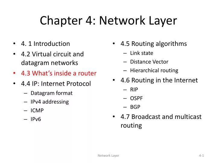
4. 1 Introduction 4.2 Virtual circuit and datagram networks 4.3 What’s inside a router 4.4 IP: Internet Protocol Datagram format IPv4 addressing ICMP IPv6. 4.5 Routing algorithms Link state Distance Vector Hierarchical routing 4.6 Routing in the Internet RIP OSPF BGP

E N D
4. 1 Introduction 4.2 Virtual circuit and datagram networks 4.3 What’s inside a router 4.4 IP: Internet Protocol Datagram format IPv4 addressing ICMP IPv6 4.5 Routing algorithms Link state Distance Vector Hierarchical routing 4.6 Routing in the Internet RIP OSPF BGP 4.7 Broadcast and multicast routing Chapter 4: Network Layer Network Layer
Router Architecture Overview Two key router functions: • run routing algorithms/protocol (RIP, OSPF, BGP) • forwarding datagrams from incoming to outgoing link Network Layer
Input Port Functions Decentralized switching: • given datagram dest., lookup output port using forwarding table in input port memory • goal: complete input port processing at ‘line speed’ • queuing: if datagrams arrive faster than forwarding rate into switch fabric Physical layer: bit-level reception Data link layer: e.g., Ethernet see chapter 5 Network Layer
Three types of switching fabrics Network Layer
Memory Input Port Output Port System Bus Switching Via Memory First generation routers: • traditional computers with switching under direct control of CPU • packet copied to system’s memory • speed limited by memory bandwidth (2 bus crossings per datagram) Network Layer
Switching Via a Bus • datagram from input port memory to output port memory via a shared bus • bus contention: switching speed limited by bus bandwidth • 32 Gbps bus, Cisco 5600: sufficient speed for access and enterprise routers Network Layer
Switching Via An Interconnection Network • overcome bus bandwidth limitations • Banyan networks, other interconnection nets initially developed to connect processors in multiprocessor • advanced design: fragmenting datagram into fixed length cells, switch cells through the fabric. • Cisco 12000: switches 60 Gbps through the interconnection network Network Layer
Output Ports • Buffering required when datagrams arrive from fabric faster than the transmission rate • Scheduling discipline chooses among queued datagrams for transmission Network Layer
Output port queueing • buffering when arrival rate via switch exceeds output line speed • queueing (delay) and loss due to output port buffer overflow! Network Layer
. RTT C N How much buffering? • RFC 3439 rule of thumb: average buffering equal to “typical” RTT (say 250 msec) times link capacity C • e.g., C = 10 Gps link: 2.5 Gbit buffer • Recent recommendation: with N flows, buffering equal to Network Layer
Input Port Queuing • Fabric slower than input ports combined -> queueing may occur at input queues • Head-of-the-Line (HOL) blocking: queued datagram at front of queue prevents others in queue from moving forward • queueing delay and loss due to input buffer overflow! Network Layer