Download
1 / 47
470 likes | 704 Views
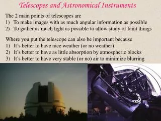
1B11 Foundations of Astronomy Telescopes and instruments. Liz Puchnarewicz emp@mssl.ucl.ac.uk www.ucl.ac.uk/webct www.mssl.ucl.ac.uk/. 1B11 Telescopes and instruments. Telescopes collect photons and bring them to a focus.

E N D
1B11 Foundations of AstronomyTelescopes and instruments Liz Puchnarewicz emp@mssl.ucl.ac.uk www.ucl.ac.uk/webct www.mssl.ucl.ac.uk/
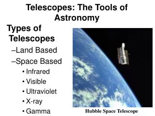
1B11 Telescopes and instruments • Telescopes collect photons and bring them to a focus. • They operate over the full range of the electromagnetic spectrum, eg radio, microwave, IR, optical, UV, X-ray, g-ray and cosmic rays. • Different techniques are used to collect the photons at different wavelengths. • This module concentrates on optical telescopes (similar technologies are used in the IR and UV).
focal plane optical axis focal length, f image lens (diameter, D) 1B11 Refracting (dioptric) Collecting area = pD2/4 Focal ratio = f/D
focal plane optical axis q q Image scale (plate scale), d=fq (for q in radians) For q in degrees: 1B11 Refracting (dioptric) focal length, f
1B11 f-ratios F-ratio = Often written as “f/f-ratio” ie f/8 is an f-ratio of 8, ie the focal length is 8x the lens (or mirror) diameter The smaller the f-ratio, the brighter the image at the focus. So for faint extended objects, the smaller the f-ratio, the better. Telescopes with small f-ratios are said to be “faster”. The amount of light gathered is determined only by D. The angular separation of objects may be magnified by adding an additional lens, ie an “eyepiece” (Galileo, 1609).
focal plane optical axis b a fo fe Angular magnification = 1B11 The eyepiece objective lens eyepiece lens NB – the image is inverted!
1B11 Reflecting (catoptric) telescopes These use mirrors to reflect and focus light (Newton, 1668). prime focus Primary mirror (paraboloid + hyperboloid)
1B11 Newtonian flat mirror Newtonian focus
1B11 Cassegrain Secondary mirror (hyperboloid) For a given f-ratio, a Cassegrain telescope is more compact. Also, the Cassegrain design lends itself to mounting heavy equipment more easily.
1B11 Diffraction effects This effect places a fundamental limit on our ability to distinguish two closely spaced objects (eg stars). Only 84% of the light is concentrated in the central spot, the rest falls in surrounding rings.
1B11 Diffraction patterns I n=1 n=1 n=2 n=2 Airy disk distance The constructive and destructive interference patterns are described according to Huygen’s Principle. For a telescope with diameter D and light with wavelength l, minima occur at positions given by: a a
1B11 Resolution n is the number or order of the minimum and m is the numerical factor for any given n (found by integrating over the light pattern). Because a is small, we may write: The light contained within the radius (84% of the total) defined by the first minimum is called the Airy disk, where and this is used to define the resolution
1B11 Rayleigh Criterion I Airy disk distance 1.22l/D I Rayleigh Criterion: A point source is said to be resolved if the closest peak of any other Airy disk falls at least as far away as its own first minimum. 1.22l/D distance
1B11 Telescope resolution Telescope diameter large Telescope diameter small Airy disk small Airy disk large Resolution high Resolution low eg Keck 10m telescope, amin = 0.014 arc sec (for l=5500A) (=1p piece at 300km) eg Fry 8inch(=20cm) telescope, amin = (1.22 x 5500x10-8)/0.20 = 3.36x10⁻⁶ radians = 0.69 arc sec (for l=5500A)
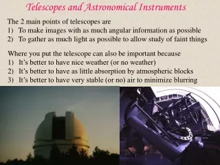
1B11 Atmospheric seeing There are other factors which limit the resolution obtainable in astronomical observations. A major factor is the turbulence in the Earth’s atmosphere which has the effect of blurring stellar images. This what causes stars to “twinkle” and is known as atmospheric seeing. Measured in arcseconds. atmosphere Good site: 0.3 - 1” (Hawaii, Chile) Generally: 1 – 2” (diff lim for D=20cm) qseeing propto ~ l-0.2 adaptive optics
1B11 Chromatic Aberration Unique to refractors – because the focal length of the lens is wavelength-dependent. Effect considerably reduced by using a compound lens Works for 2 colours Crown glass, m low, convex Flint glass, m high, plano-concave
1B11 Spherical aberration Light rays which are parallel to the optical axis of a lens or spherical mirror, but which lie at different distances from the axis, are brought to different foci. (exaggerated for clarity) centre focus edge focus Paraboloidal mirrors do not suffer from aberration, but spherical mirrors have a wider field of view, are coma-free and have low f-ratios.
1B11 Catadioptric telescopes • Spherical aberration from mirrors may be corrected by adding corrective plates or lenses (eg Hubble Space Telescope). • There are two main designs of telescope which use these corrective elements: • Schmidt telescopes – where a thin corrector plate is placed at the centre of curvature of the mirror • Maksutov cameras – a spherical meniscus lens is inserted in the light’s path. Hubble Space Telescope
1B11 Schmidt telescope Corrector lens In the Schmidt design, a thin corrector plate or lens is placed at the centre of curvature of the (spherical) mirror. The features of the plate shown in the diagram are exaggerated for clarity. Most suitable as a camera and often used as survey instruments, eg Palomar Observatory Sky Survey, UK Schmidt survey. Focal surface Spherical mirror
1B11 Maksutov cameras The meniscus lens has a negative long-focus and spherical surfaces. It produces its own spherical aberration which cancels out the mirror’s. It can also be made achromatic so a Maksutov camera can be free of spherical and chromatic aberrations. meniscus correcting lens focal surface spherical mirror
1B11 Coma Point sources which do not lie along the axis of a lens or non-spherical mirror, will look comet-like (or fan-like) – this effect is called “coma” and is because the focus of off-axis light depends on the path it takes through the lens (or where it falls on the mirror). Consider the lens as a series of annuli. Each annulus produces an annular image but these lie at different foci.
1B11 Coma (cont.) The coma may point towards the axis (positive coma) or away from it (negative coma). Spherical mirrors do not suffer from coma because the mirror always presents the same geometry to the point source, irrespective of off-axis angle. Parabolic mirrors, which do not have spherical aberration, do suffer from coma, so are only effective in a narrow field around the optical axis. In Ritchy-Chretien (modified Cassegrain) telescopes, spherical aberration and coma are both removed, by using hyperbolic primary and secondary mirrors.
1B11 Astigmatism If the mirror or lens is stressed or poorly machined, the focal length along one axis of the mirror may be different to focal length along another, resulting in a spread of the image in the focal plane.
1B11 Telescope mounts • Telescopes must be free to move about two mutually perpendicular axes in order to cover the whole sky. • There are two main types: • Equatorial – one axis is aligned with the celestial poles so you need only track in one axis (ie in HA) • Altazimuth – telescope moves in (local) altitude and azimuth, so is simpler to design but has to be tracked in two axes
1B11 Equatorial mounts equator HA NCP declination f = latitude f SCP Only need to track in HA and there is no field rotation (direction of North in the focal plane is fixed). But it is complex and expensive to build – especially for large telescopes.
Cassegrain focus Coude focus 1B11 Coude focus Polar axis Dec axis The Coude focus is accessed by taking the beam out through the Dec axis. Useful for very large and massive instruments, eg spectrographs.
Nasmyth focus 1B11 Altazimuth mounts Horse-shoe mount Altitude axis local vertical The design is simple, but it must track in both axes and the field rotates. The largest (8-10m) telescopes have altaz mounts with Cassegrain and Nasmyth foci
1B11 Instruments and detectors Instruments and detectors analyze and record the light focussed by a telescope. instrument astronomer detector telescope • Typical instruments: • Camera • Spectrograph • Polarimeter • Photometer • Detectors: • Charge-coupled devices (CCDs) • Photographic plates
1B11 Spectrographs Narrow-band filters can be used to examine a small wavelength range of a source, but to look over a wide wavelength range in very fine detail, a spectrograph is used. Light at the focal plane is dispersed and focussed onto a detector. A narrow slit is used to select the region of the image for analysis. The light is collimated using a mirror or lens, and directed towards a dispersing element (diffraction grating or prism). The dispersing element spreads out the light into a spectrum, which is then focussed onto a detector (usually a CCD) by a lens.
q For normal incidence: n = order number l = wavelength d = groove spacing 1B11 Spectrograph layout slit in telescope focal plane collimator mirror beam from telescope CCD diffraction grating imaging lens
1B11 Charge-coupled device (CCD) CCDs are solid state detectors with typically1k x 1k light sensitive elements (pixels) each of which is usually about 10-20mm square. The pixels are electrically insulated from each other and a charge accumulates in each one. The amount of charge is proportional to the intensity of light falling on it. The charge distribution is the same as the light distribution.
1B11 Structure of a CCD electrodes photon pixel f3 f2 f1 0.1mm insulator (SiO2) electron p-type semi-conductor (silicon crystal) hole A photon strikes the silicon crystal and an electron, which normally settles in the valence band, is excited into the conduction band. Here the electrons are free to migrate, leaving behind a “hole”. The electrodes are maintained at pd’s of about 10V and attract the electrons, which accumulate under the electrodes until the CCD is read out.
f3 f2 f1 current induced charge accumulated incident photons image reconstruction 1B11 CCD readout While collecting data, only f2 is held high, so electrons accumulate there. To read out the chip, the voltages are cycled through the electrodes so that the electrons shift along (or down) until they reach the edge.
1B11 CCD quantum efficiency The quantum efficiency of a CCD is defined to be the ratio of recorded (ie detected) photons to the number of incident photons. Q.E. is a function of wavelength but may be as high as 80-90% over much of the visible spectrum.
1B11 UV and IR Telescopes Telescopes in the ultraviolet and infra-red are similar in concept to optical telescopes, but are orbiting space observatories – launched beyond the Earth’s atmosphere which is opaque at these wavelengths. Conventional CCDs are not sensitive, particularly at wavelengths longer than 1mm, so different types of crystal are used, eg indium antimonide and gallium-doped germanium. Hubble Space Telescope Imaging Spectrograph Near-IR imaging on the UK Infra-Red Telescope (UKIRT) The next generation of space IR observing with the JWST
Cassegrain detector prime focus In the radio, l is large, so D must be large for reasonable resolution. eg the Jodrell Bank 76m dish has a resolution of 0.19 degrees. Recall that the telescope resolution, a, is given by: 1B11 Radio astronomy D Telescope resolution
1B11 Interferometry Radio telescopes get around this problem – and produce the most finely detailed images of the sky at any wavelength – using the technique of interferometry.
With a minimum of two telescopes, can map the pattern, but results are 1-D and limited. Using multiple telescopes and/or the Earth’s rotation, can map out the other dimension as well – this is called aperture synthesis. The Rayleigh Criterion (ie the resolution for this technique) is: where L is the spacing of the telescopes and qmin is the resolution. 1B11 Interferometry
q q 1B11 Basic interferometry The effective baseline, L = a cos ZD (where a is the distance between the telescopes, and ZD is the zenith distance of the source.) a L signals combined
1B11 A brief history of interferometry • The success of radio interferometry was first demonstrated in the 1940’s. • It was based on experiments into optical interferometry first developed by Michelson in 1890. • Australian and British astronomers further developed the technique in the 1950’s and 1960’s. Martin Ryle and Antony Hewish obtained the 1974 Nobel Prize for Physics for their work on Earth aperture synthesis. • Radio telescopes around the world join together to form enormous Earth-size “telescopes”; this is Very Long Baseline Interferometry. • There are plans to extend the baseline further – into space!
1B11 More information on radio astronomy The National Radio Astronomy Observatory (NRAO) The NRAO guide to radio astronomy The Jodrell Bank Observatory in Manchester Probably the biggest astronomical telescope in the world. The Very Long Baseline Array. On the Development of Radio Interferometry (by Bob Tubbs, Cambridge).
1B11 X-ray astronomy X-rays are absorbed by the Earth’s atmosphere, so we need to go into space to make observations. Originally, sounding rockets were used to make the first X-ray observations, but these were limited in their accuracy and could only make a relatively short programme of observations, before it fell back into the atmosphere. Today, we have a powerful array of X-ray space observatories, and X-ray astronomy is a very fast-moving science. NASA’s Chandra X-ray observatory ESA’s XMM-Newton The Rossi X-ray Timing Explorer
If an X-ray hits a mirror at a very high angle of incidence, it will be reflected.So if you construct a conical mirror which is almost cylindrical, it will bring the X-rays to a focus. These are called “grazing incidence” mirrors. 1B11 X-ray imaging If an X-ray hits a mirror, it will pass straight through unless it hits the mirror at a very high angle of incidence.
1B11 X-ray mirrors X-ray mirrors are conical, almost cylindrical. The design currently used is the Wolter mirror, whose profile is parabolic in the wider section and hyperbolic in the narrower section. paraboloid hyperboloid This diagram is exaggerated for clarity – in XMM-Newton the mirrors are typically 0.3-0.7m in diameter and the focal point lies 7m away.
1B11 Nesting mirrors Because they are almost cylindrical, X-ray mirrors present a very small collecting area to incoming radiation. To improve the light-collecting area, many mirrors are nested together, eg each telescope module in XMM-Newton contains 58 mirrors, stacked like Russian dolls.
1B11 Focal plane instruments Chandra and XMM-Newton are imaging X-ray telescopes and carry an array of instrumentation, including special X-ray sensitive CCDs and grating spectrometers. On XMM-Newton, there are 7 600x600 pixel MOS CCDs in each MOS array, arranged to match the focal plane of the telescope. There is also a pn CCD – a fixed format X-ray CCD chip which uses a different kind of technology. Chandra imaging resolution is about 1arcsec – rivalling that of the best ground-based optical telescopes. XMM-Newton is sensitive enough to reach to ~1Myr after the Big Bang.