OPO OVERVIEW
Explore second harmonic, difference frequency, and optical parametric oscillation with phase matching using periodically poled crystals for broadband parametric amplification and chirped pulse amplification.

OPO OVERVIEW
E N D
Presentation Transcript
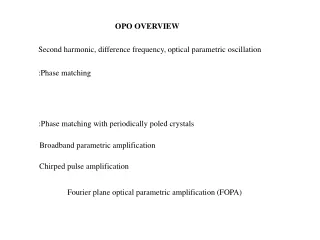
OPO OVERVIEW Second harmonic, difference frequency, optical parametric oscillation :Phase matching :Phase matching with periodically poled crystals Broadband parametric amplification Chirped pulse amplification Fourier plane optical parametric amplification (FOPA)
Second harmonic, difference frequency, optical parametric oscillation LOSS GAIN GAIN OPG SF DF or OPO or OPA
Second harmonic, difference frequency, optical parametric oscillation What is the difference between population inversion gain and optical parametric gain? Population inversion OPG Lasts after the pump Instantaneous Energy dissipation no dissipation in matter (relaxation mechanisms) Analogy?
Ip Ip TIME TIME G A I N TIME Analogy: population inversion gain versus optical parametric gain G A I N TIME
dE2 = a E12 dz dE1 = -a E2E1* dz Phase matching Phase matching in second harmonic generation TYPE I Fundamental Phase matching Second harmonic SHG E2 Different wavelengths Distance z ENERGY EXCHANGE ALWAYS FROM 1 TO 2
dE2 = a EoEe dz dEe dEo = -a E2Eo* = -a E2Ee* dz dz Phase matching Phase matching in second harmonic generation TYPE II SHG Phase matching Eo Ee THE SIGN OF ENERGY EXCHANGE CAN CHANGE Distance z
Tuning the crystal length for optimum short pulse compression LONG CRYSTALS = HIGHER CONVERSION LONG CRYSTALS = NARROWER BANDWIDTH The obvious solution for short pulses: short crystals? Not always! One can use long crystals to compress pulses down to femtoseconds. THE GENERATED PULSES ARE SHORTER THAN THE FUNDAMENTAL, AND THAN THE INVERSE BANDWIDTH OF THE SECOND HARMONIC PROCESS. Where does one get the bandwidth? From the amplitude modulation of the pump, as the pump is depleted at a faster rate than the pump risetime.
Compression in SHG Motion of pulses in the frame of reference of the second harmonic Weak pulses: the second harmonic broadens as the overlap of the two fundamental pulses increases
Compression in SHG Motion of pulses in the frame of reference of the second harmonic Strong pulses The trick: sum frequency group velocity between that of fundamental o and fundamental e
dE2 = a E12 dz dE1 = -a E2E1* dz Phase matching with periodically poled crystals Use the orientation for maximum NL coefficient. Periodically reverse the sign of the coefficient (a), when SHG E2 sin Dk z = sin (k2 - 2k1z) changes sign Distance z Advantage: Large nonlinearity Disadvantage: Periodic structure Narrow band
(a) (b) (c)
Find the angles? SNLO CHIRP AMPLIFICATION
There are two solutions to the narrow bandwidth of Periodically Poled crystals: 1. Pole the crystal “non-periodically” “ENGINEERABLE COMPRESSION OF ULTRASHORT PULSES BY USE OF SECOND HARMONIC GENERATION IN CHIRPED-PERIOD-POLED LITHIUM NIOBATE”, Optics Letters 22, 1341 (1997) “SIMULTANEOUS FEMTOSECOOND-PULSE COMPRESSION AND SHG IN APERIODICALLY POLED KTiOPO4”, Optics Letters 24, 1071 (1999) 2. Convert the spectrum piece by piece x Periodically poled crystal of period changing with x.
Laser source Other solution: use many crystals for each wavelength range grating L y grating This is part of OPCPA
LASER DAMAGE CHIRPED PULSE AMPLIFICATION AMPLIFIED SHORT PULSE LINEAR DISPERSION (+) LINEAR DISPERSION (-) SHORT PULSE GAIN If the parametric gain is sufficiently broad for the short pulse, it is also sufficiently broad for the dispersed pulse. THE PARAMETRIC GAIN HAS NO ENERGY STORAGE: THE DURATION OF HAVE TO BE MATCHED PUMP SIGNAL PUMP DEPLETION: “DIP” IN PUMP. TECHNICAL CHALLENGE: PUMP 100 ps OR LESS SIGNAL STRETCHED TO > 100 ps.
Motivation for 5-fs (2-cycle) lasers Relativistic HHG Generation of single attosecond light and electron pulses in gas and plasma medium 5 fs cos Gas harmonics 20 fs 5 fs cos 5 fs sin l3 regime N. M.Naumova et al., Phys. Plas. 12, 056707 (2005) G. D. Tsakiris et al., New J. Phys. 8, 19 (2006) A. Baltuska et al., IEEE J. of Sel. Top. in Quantum Electronics 9, 972 (2003) A. Baltuska et al., IEEE J. of Sel. Top. in Quantum Electronics 9, 972 (2003) G. D. Tsakiris et al., New J. Phys. 8, 19 (2006) A. Baltuska et al., IEEE J. of Sel. Top. in Quantum Electronics 9, 972 (2003)
Optical parametric chirped pulse amplification (OPCPA) Idler Pump Signal BBO Advantages • Broadgainbandwidth, • supporting few-cycle pulses • Good contrast achievable • ... * D. Herrmann et al. Opt. Lett., 34, 2459 (2009) F. Tavella et al.Opt. Lett. 32, 2227(2007) S. Witte et al.Opt. Express 14, 8168(2006) S. Adachi et al. Opt. Express 16, 14341 (2008)
Synthesizer principles • Parallel synthesis • Pro: • Shorter „beam path“ • Simple narrow bandwidth mirrors • Contra: • Interferometric stability needed • Very sensitive high rep.rate • Broad bandwidth mirrors after beam combination • Similar principle: frequency domain OPA • Serial synthesis • Pro: • No special requirements on stability • Insensitive • Contra: • Longer „beam path“ • Broad bandwidth mirrors Il l • S.-W. Huang et al.Nat. Photon 5, 475 (2011) • C. Manzoni et al. Opt. Lett. 37, 1880 (2012) • B. E. Schmidt et al. Nat. Commun. 5, 3643 (2014) • D. Herrmann et al., Opt. Exp.18, p. 18752 (2010) • A. Harthet al. Opt. Express 20, 3076 (2012)
Multi-10-TW sub-5-fs Optical Parametric Synthesizer − Relativistic intensity sub-5-femtosecond laser pulses and their applications Laszlo Veisz1, Daniel Rivas1, Gilad Marcus1, Xun Gu1, Daniel Cardenas1, Jiancai Xu1, Julia Mikhailova1, Alexander Buck1,2, Tibor Wittmann1, Christopher M. S. Sears1, Daniel Herrmann3, Olga Razskazovskaya2, Vladimir Pervak2, Ferenc Krausz1,2 1 Max-Planck-Institut für Quantenoptik, Hans-Kopfermann-Str. 1, 85748 Garching, Germany 2 Ludwig-Maximilians-Universität München, Am Coulombwall 1, 85748 Garching, Germany 3Lehrstuhl für BioMolekulare Optik, Department für Physik, Ludwig-Maximilians-Universität,Oettingenstrasse 67, 80538 München, Germany
Laser source Fourier plane optical parametric amplification (FOPA) Faux pas grating L y grating This is part of OPCPA PUMP
A collimated Gaussian beam of 2 mm diameter FWHM, 800 nm, is incident on a pair of gratings of 1700 grooves/mm, at an angle of incidence of 30 degrees (see Fig. ). The spacing between the gratings is L = 10 cm. After the gratings, the diffracted beam is incident on 4 independent modulators, each of height Δy = 2 mm. Assuming a Gaussian pulse of g = 40 fs duration, calculate the duration and chirp of the pulse entering each 2 mm section (you are sampling a fraction of the spectrum of the pulse diffracted by the gratings). You can make abstraction of the spatial problem for this question. Two approaches possible: (a) see which wavelength correspond to each section boundaries. That defines the spectrum. The inverse of the spectrum gives the pulse duration (b) Calculate the second order dispersion of the pair of gratings. That give the pulse broadening and chirp introduced by the pair of gratings.
(b) Calculate the second order dispersion of the pair of gratings. That give the pulse broadening and chirp introduced by the pair of gratings.
TIME SPACE
(b) Calculate the second order dispersion of the pair of gratings. That give the pulse broadening and chirp introduced by the pair of gratings. If m is the order of diffraction, the angle of incidence and the diffraction angle are related through the grating equation
(a) see which wavelength correspond to each section boundaries. That defines the spectrum. The inverse of the spectrum gives the pulse duration