Download
1 / 46
460 likes | 604 Views
P14251 Underwater Acoustic Communication. Greg Davis Scott Hambleton Jon Holton Chris Johnson Chris Monfredo. 12/10/13. Rochester Institute of Technology. 1. Underwater Acoustic Communication. Agenda Design Updates/Proof of Concept Software Components Drawings (EE) BOM (EE)

E N D
P14251 Underwater Acoustic Communication Greg Davis Scott Hambleton Jon HoltonChris Johnson • Chris Monfredo 12/10/13 Rochester Institute of Technology 1
Underwater Acoustic Communication Agenda • Design Updates/Proof of Concept • Software Components • Drawings (EE) • BOM (EE) • Drawings (ME) • BOM (ME) • Final Cost Analysis • Final Risk Analysis • Test Plans • MSD II Schedules 12/10/13 Rochester Institute of Technology 2
Underwater Acoustic Communication • Frequency Shift Keying: • Produces four different frequencies corresponding to 00, 01, 10, 11 • SD Simple modulation and demodulation schemes and circuitry • Quick and efficient set up and delivery times Schedules 12/10/13 Rochester Institute of Technology 3
Underwater Acoustic Communication • Frequency Shift Keying: • Modulation: • Theory-produce four different frequencies that each represent a different two bit symbol. These frequencies will be gray coded such that only a maximum of one bit error can occur per demodulation error. • After compression and redundancy, we need to send 9768 kbps to meet our 15 kbps customer requirement. This indicates that the lowest possible frequency that can be used is 14.4 kHz. • 29 kHz = 00 • 34 kHz = 01 • 39 kHz = 11 • 44 kHz = 10 12/10/13 Rochester Institute of Technology 4
Underwater Acoustic Communication • Frequency Shift Keying: • Modulation: • To produce the four needed frequencies, properties of a square wave can be exploited. The main property being used is that in frequency, a square wave, is sync function. A sync function has a large amplitude at the center frequency and multiple harmonics that theoretically occur every 3*fc • Using a sharp band pass filter will allow us to keep the large portion of the signal that occurs at the center frequency while removing • all of the other harmonics • To generate the needed frequency response, an LC • band pass filter will be used 12/10/13 Rochester Institute of Technology 5
Underwater Acoustic Communication • Frequency Shift Keying: • Modulation: • The LC band pass filter has a center frequency at 1/sqrt(LC), and a bandwidth of 1/(C*RL). Since the output of our filter will be fed into an amplifier with theoretical infinite input resistance, our bandwidth will be very small; which is desirable. • By adjusting the input resistance, we can also adjust the sharpness of each filter • Each filter will be fed by a clock pin coming from the RPi, that will provided the square wave at each of the four desired frequencies • The output of the four band pass filters will be fed into a 4:1 mux whose output will be controlled via an enable and two addressing pins 12/10/13 Rochester Institute of Technology 6
Underwater Acoustic Communication Frequency Shift Keying: Modulation: 12/10/13 Rochester Institute of Technology 7
Underwater Acoustic Communication • Frequency Shift Keying: • Demodulation: • To demodulate we are looking to decipher the four different frequencies in order to obtain the original binary message • This will be done by taking the incoming signal from the hydrophone, band passing around our frequency range, and then passing the analog signal through an analog to digital converter. The output of the ADC will then be fed back to a pin on the RPi. • The DFT will then be performed on the incoming signal in order to determine the largest frequency component. Based on the frequency and the amplitude at this frequency, the incoming message will be decoded. • The DFT will be performed using the FFTW C programming package developed by MIT 12/10/13 Rochester Institute of Technology 8
Underwater Acoustic Communication • Frequency Shift Keying: • Demodulation: • The FFTW package allows the user to do one or multiple dimension FFT’s with a very simple to use library • This package is also optimized for multithreading and also gives the capability to determine the most optimum way in which to take the FFT of the current signal. #include <fftw3.h> { fftw_complex *in, *out; fftw_plan p; ... in = (fftw_complex*) fftw_malloc(sizeof(fftw_complex) * N); out = (fftw_complex*) fftw_malloc(sizeof(fftw_complex) * N); p = fftw_plan_dft_1d(N, in, out, FFTW_FORWARD, FFTW_ESTIMATE); ... fftw_execute(p); /* repeat as needed */ ... fftw_destroy_plan(p); fftw_free(in); fftw_free(out); } 12/10/13 Rochester Institute of Technology 9
Underwater Acoustic Communication Frequency Shift Keying: Demodulation: periods: 3 FS: 2.25 MHz 12/10/13 Rochester Institute of Technology 10
Underwater Acoustic Communication • Dish Concept: • Use parabolic collector • around hydrophone. • Center hydrophone at • focal point. • Increase gain from transmitter. Parabolic Antenna Concept Radartutorial .eu 12/10/13 Rochester Institute of Technology 11
Underwater Acoustic Communication • Initial Dish Design: • Mounts on top of housing • Made from plastic or metal • 12” Diameter to increase • gain 12/10/13 Rochester Institute of Technology 12
P14251 Underwater Acoustic Communication • CE Overview • Software Architecture • Control unit flowchart and pseudo-code • Error Detection/Correction • Framing Information • Data Rate Analysis 11/26/13 Rochester Institute of Technology 13
P14251 Underwater Acoustic Communication Software Architecture 11/26/13 Rochester Institute of Technology 14
P14251 Underwater Acoustic Communication Control Unit Pseudo-Code 11/26/13 Rochester Institute of Technology 15
P14251 Underwater Acoustic Communication Control Unit Pseudo-Code 11/26/13 Rochester Institute of Technology 16
P14251 Underwater Acoustic Communication Control Unit Pseudo-Code 11/26/13 Rochester Institute of Technology 17
P14251 Underwater Acoustic Communication Error Detection and Correction • Hybrid Scheme: ECC and ARQ • EEC Implementation: BCH vs. Reed Solomon • BCH is easier to implement, but requires a much larger amount of redundancy • Reed-Solomon is more complex, but overall much better and requires only 20% redundancy (to correct 10% of errors) 11/26/13 Rochester Institute of Technology 18
P14251 Underwater Acoustic Communication Error Detection and Correction • Reed Solomon encodes k symbols into n codewords • n – k = 2t • Errors are corrected at the symbol level. If a symbol has 4 bits and all of them are wrong, it only counts as one error. • Can vary the code word size with the number of bits per symbol • RS(255, 212) with 4 bits/symbol, RS(1023, 853) with 1 bit/symbol, etc. 11/26/13 Rochester Institute of Technology 19
P14251 Underwater Acoustic Communication Error Detection and Correction • Encoding: LFSR based implementation is extremely simple and fast. Will translate well to C 11/26/13 Rochester Institute of Technology 20
P14251 Underwater Acoustic Communication Error Detection and Correction • Decoding is more complex, but efficient algorithms exist that will help significantly 11/26/13 Rochester Institute of Technology 21
P14251 Underwater Acoustic Communication • Frame Sentinels • Sentinels are a unique pattern of bits that signify the start and end of the framei.e. 01110 –data– 01110 • When preparing the frame for transmission, if the pattern appears anywhere in the data, bit stuffing is used to eliminate it (i.e. 01110 -> 011010) • Commonly used sentinel which we’ll use is 01111110 • Frame Header • 1 bit to signify the type of frame: control or message • 1 bit that gets flipped each time a new frame is sent 11/26/13 Rochester Institute of Technology 22
P14251 Underwater Acoustic Communication • Control frame formats • Since it’s especially important to interpret control frames correctly, 4 bits are used to display the unique patterns • 0000 – Request to Send (RTS) • 0110 – Clear to Send (CTS) • 1001 – Acknowledgement (ACK) • 1111 – Done (Signifies that all frames have been sent) • These 4 bits + the 2 header bits can be encoded with an RS(7, 3) code (2 bits per symbol) 11/26/13 Rochester Institute of Technology 23
P14251 Underwater Acoustic Communication • Frame Sizes • - Control Frame: 16 (sentinels) + 14 (data) = 30 bits- Message Frame: 16(sentinels) + X+2 (message) = 18+X bits • Propagation delay (20ms for 30m distance) limits the number of frames that can be sent. • For 15kb/s, the maximum number of message frames =9 frames, each containing 1k encoded information bits • Increase X to ~1023 bits for Reed-Solomon Encoding 11/26/13 Rochester Institute of Technology 24
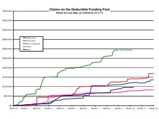
P14251 Underwater Acoustic Communication 11/26/13 Rochester Institute of Technology 25
P14251 Underwater Acoustic Communication • Data Rate Analysis – Code Overhead • From SSDR: Compression time is expected to be negligible • Encryption time is a non-factor • FFTW benchmarking info suggests very quick performance times • Error Encoding time is negligible • Error Decoding time may take a bit longer, but millions of clock cycles are available to work with. • * We may be able to further lower the number of message frames to eliminate propagation delays. This adds slightly more complexity to error handling. 11/26/13 Rochester Institute of Technology 26
Underwater Acoustic Communication 12/10/13 Rochester Institute of Technology 27
Underwater Acoustic Communication 12/10/13 Rochester Institute of Technology 28
Underwater Acoustic Communication 12/10/13 Rochester Institute of Technology 29
Underwater Acoustic Communication 12/10/13 Rochester Institute of Technology 30
Underwater Acoustic Communication 12/10/13 Rochester Institute of Technology 31
Underwater Acoustic Communication 12/10/13 Rochester Institute of Technology 32
Underwater Acoustic Communication Mechanical Drawings • Assembly • Sheet Metal Housing • Mounting Plate • Front and Back covers 12/10/13 Rochester Institute of Technology 33
Underwater Acoustic Communication Assembly Drawing 12/10/13 Rochester Institute of Technology 34
Underwater Acoustic Communication Sheet Metal Housing 12/10/13 Rochester Institute of Technology 35
Underwater Acoustic Communication Mounting Plate 12/10/13 Rochester Institute of Technology 36
Underwater Acoustic Communication Back Cover 12/10/13 Rochester Institute of Technology 37
Underwater Acoustic Communication Front Cover 12/10/13 Rochester Institute of Technology 38
Underwater Acoustic Communication Mechanical BOM • Total Mechanical cost: $113 + Housings and Dishes 12/10/13 Rochester Institute of Technology 39
Underwater Acoustic Communication • B117-11 Spray Test Results: • 6061 Aluminum preformed worst. • Naval Brass, ABS Plastic, and 316SS all had no noticeable effects of corrosion • 316SS Best choice for cost and machinability. 12/10/13 Rochester Institute of Technology 40
Underwater Acoustic Communication Cost Analysis • MSD I Test Cost: $100 • Mechanical Component Cost: $113 + Housings • Electrical Component Cost: $1105 + PCBs • Total Budget: $1750 • $432 remainder for shipping and emergencies 12/10/13 Rochester Institute of Technology 41
Underwater Acoustic Communication Electrical Test Plans • Power Converters • <5% Ripple at 1A load for 5V • <1% Ripple at 1A load for 3.3V • Power Amplifier • Adjustable Gain • Find resistance for 10W • AGC • 1V Amplitude for any input • LC Filters • Adjust values 12/10/13 Rochester Institute of Technology 42
Underwater Acoustic Communication Software Test Plans • Unit test all code • Device testing : make sure code actually runs on the Raspberry Pi • Wired device testing : make sure both devices can communicate via wired connection before attempting wireless • Turn functionalities on and off to see that they make a difference 12/10/13 Rochester Institute of Technology 43
Underwater Acoustic Communication Mechanical Test Plans 12/10/13 Rochester Institute of Technology 44
Underwater Acoustic Communication Risk Analysis 12/10/13 Rochester Institute of Technology 45
Underwater Acoustic Communication MSD 2 Schedule 12/10/13 Rochester Institute of Technology 46