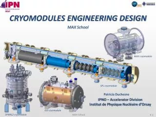
CRYOMODULES ENGINEERING DESIGN
CRYOMODULES ENGINEERING DESIGN. MAX School. MAX cryomodule. SPL cryomodule. Patricia Duchesne. IPNO – Accelerator Division Institut de Physique Nucléaire d’Orsay. ESS cryomodule. SPIRAL2 cryomodule. CONTENTS. INTRODUCTION BASIC FUNCTIONS Main components

CRYOMODULES ENGINEERING DESIGN
E N D
Presentation Transcript
CRYOMODULES ENGINEERING DESIGN MAX School MAX cryomodule SPL cryomodule Patricia Duchesne IPNO – Accelerator Division Institut de Physique Nucléaire d’Orsay ESS cryomodule SPIRAL2 cryomodule MAX School
CONTENTS • INTRODUCTION • BASIC FUNCTIONS • Main components • Cryogenic scheme of a cryomodule • Thermal aspects • Mechanical aspects • Different concepts of supporting • Assembly process • CONCLUSION MAX School
CONTENTS • INTRODUCTION • BASIC FUNCTIONS • Main components • Thermal aspects • Mechanical aspects • Different concepts of supporting • Assembly process • Cryogenic scheme of a cryomodule MAX School
DESIGN OF A CRYOMODULE A cryomodule is an unit cell of an accelerator that contains some Superconducting Radio Frequency (SRF) cavities and all the components required to their operation at cryogenic temperatures. Warm quadrupole SPL Layout (2010): segmented architecture INTRODUCTION Cryomodule (3 cavities =0.65 ) Cryomodule (8 cavities =1 ) SPL Cryomodule (8 cavities b=1) MAX School
DESIGN OF A CRYOMODULE A cryomodule is: A part of an accelerating section A part of an overallcryogenic system Independent cryogenic subsystems or connected to each other: The overall cryogenic system impacts on the segmentation of the accelerator and therefore on the cryomodule Type of cavities, number of cavities, focusing elements: The accelerator design determines in part the composition of the cryomodule The design of a cryomodule depends on several parameters: INTRODUCTION • The accelerator design (accelerating and guide components, sequence) • The overall cryogenic system(independent subsystems or connected each other) • The expected performance of the accelerator (reliability, availability ...) • The cost • Manufacturing cost: high filling factor (long cryomodule, short interconnections) • Operating cost: static heat losses (long cryomodules cryogenically connected) MAX School
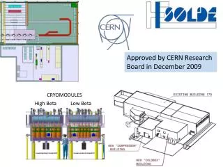
CRYOMODULES/CRYOSTATS, SEVERAL EXAMPLES GANIL-SPIRAL2 FRANCE ESS-LUND-SWEDEN DESY- HAMBURG-GERMANY Beginning in 2019 J-PARC-TOKAI-JAPAN INTRODUCTION SNS, TENNESSEE-USA LHC – CERN-SWITZERLAND CEBAF, J-LAB-VIRGINIA-USA MAX School
CONTENTS • INTRODUCTION • BASIC FUNCTIONS • Main components • Thermal aspects • Mechanical aspects • Different concepts of supporting • Assembly process • Cryogenic scheme of a cryomodule MAX School
BASIC FUNCTIONS • A cryogenic environment for the cold mass • Cryogenic distribution (piping, phase separator, valves): He coolant (liquid or gas) at required temperatures • The vessels of the cavities/magnets are filled with liquid helium at 4K or lower temperature. • The active thermal shield can be cooled with helium gas • The magnetic shield • The power coupler • Thermal insulation (shield, vacuum and superinsulation) against all sources of heat transfer from room temperature to cryogenic temperature • Heat conduction • Heat transfer by convection • Thermal radiation BASIC FUNCTIONS • Supporting and positioning components • Structural support of the cold mass • Precise alignment of the cavities regarding the beam and reproducibility with thermal cycles • Interface between the cold mass and the room temperature • Connection points for integrated systems: current, RF, instrumentation and cryogenics • Magnetic protection against the magnetic field from the earth and other sources MAX School
CONTENTS • INTRODUCTION • BASIC FUNCTIONS • Main components • Thermal aspects • Mechanical aspects • Different concepts of supporting • Assembly process • Cryogenic scheme of a cryomodule MAX School
MAIN COMPONENTS • Vacuum vessel • Thermal Insulation • Interface Vacuum vessel Cryogenicpiping String of cavities • Supporting components • Supporting and positioning • Thermal shields • Thermal Insulation MAIN COMPONENTS • Cryogenic piping • Cryogenic environment 1,80m • Magnetic shield • Magnetic protection Thermal shield Magneticshield Supporting components ESS Spoke Cryomodule • Cold mass (cavities, magnets) MAX School
COLD MASS (CAVITIES, MAGNETS) String of dressed superconducting RF cavities (equipped with their helium vessel and their ancillaries) and possibly presence of superconducting magnets of focalization SC Cavity: Pure niobium, Helium vessel: titanium, stainless steel • Assembly string: ultra cleanliness required for the internal walls of the cavity and those of the coupler The string is prepared in clean room with mounting of the power couplers, warm cold transitions and vacuum valves at the extremities • Cavity: elliptical, spoke, quarter-wave, and half-wave resonators Inter cavitybellows Warm cold transition Heliumvessel MAIN COMPONENTS Vacuum valve Cold Tuning system Power coupler ESS String of spoke cavities MAX School
MAGNETIC SHIELD Providing a protection against the earth magnetic field and fields from other sources (ex: magnet stray fields) AMUMETAL (nickel-iron alloys) at room temperature, CRYOPERM at low temperatures • Around the cavity (shield at low temperature) • To be efficient, the shield has to be cooled before the critical temperature of the cavity (superconductivity) • Around all the components of the vacuum vessel (shield at room temperature) Magnetic shield with a cooling system between two walls (Cryoperm): magnetic shield (Cryoperm) around each cavity: MAIN COMPONENTS SPL Short Test Cryomodule ESS Spoke Cryomodule MAX School
CRYOGENIC PIPING Pipes providing cryogenic fluids at different temperatures Stainless steel, aluminium or copper • Cryogenic piping depends on the cryogenic distribution system of the accelerator • (see § Cryogenic scheme of a cryomodule): • - Cryomodule cryogenically connected to form a cryo-string (minimizing the number of cryogenic feeds) Cooling and return pipes integrated into the cryomodule • - Cryomodule cryogenically independent Each cryomodule is connected to the Cryogenic Transfer Line (CTL) via a valve box. • Cryogenic piping provides cryogenic fluids to: • - Thermal shield • - Magnetic shield • - Power coupler • - Warm to cold transition • - Cavity Cryogenic valves Biphasic tube Thermal shield tube MAIN COMPONENTS Warm to cold transition pipe Coupler tube Magnetic shield tube MAX School
THERMAL SHIELDS Active thermal shield at intermediate temperature (50-80K) Passive thermal shield (Multi Layer Insulation) To minimize the radiation heat transfer • Metallic shield: aluminium or copper actively cooled at 50K-80K • Its design is strongly conditioned by the problematic of thermal contractions and of assembly • MLI (Multi Layer Insulation): composed of some reflective layers (aluminium) alternated of some insulating spacers (mylar) placed on: • the surface of the thermal shield (~ 30 layers) • the surface of the components at lower temperatures (~ 10 layers) Thermal shield MAIN COMPONENTS MLI MAX School
SUPPORTING COMPONENTS Supports maintaining all the components in the vacuum vessel Resin, composite, Titanium alloy, ... • Stiff and stable over the lifetime: Support the weight of the components and maintain the good alignment of the cold mass • Warm to cold transitions: limit conduction heat transfer MAIN COMPONENTS Tie rods MAX School
VACUUM VESSEL Metallic vessel containing the insulating vacuum to minimize convection heat transfer Carbon steel, stainless steel, aluminium (pressure requirements, magnetic shield potential, the cost ...) • A tight structure: guarantee 10-7 bar inside the vacuum level • A rigid structure: No risk of buckling • It must provide: • Floor fixing supports • Ports for coupler, cryogenic piping, instrumentation ... • Attachment points of the cold mass • Supports for alignment • ... Instrumentation port Safety valve Optical alignment Vacuum vessel MAIN COMPONENTS Cover ends Attachment point of the cavity coupler port Supports MAX School
VACUUM VESSEL ESS Spoke Cryomodule: Examples of vacuum vessel studied at IPNO: MAX Spoke Cryomodule: SPIRAL2 Cryomodule B: 1,3m 1,2m 2,8m ESS Elliptical Cryomodule: 1,9m 2,8m 1,2m MAIN COMPONENTS ~ 6,5m 1,16m SPL Short test Cryomodule: 0,8m ~ 7m MAX School
CONTENTS • INTRODUCTION • BASIC FUNCTIONS • Main components • Cryogenic scheme of a cryomodule • Thermal aspects • Mechanical aspects • Different concepts of supporting • Assembly process MAX School
COOLING MODES Helium phase diagram • SRF cavities are generally cooled • with an isothermal saturated bath (equilibrium vapour and liquid phases): • T = 4.2K and P = 1 bar • T < 2.1K and P < 30 mbar • Stable pressures, limitation of pressure fluctuations that have an impact on the cavity frequency • A bath at T< 4.2K is generated by isenthalpic expansion, through Joule-Thomson valves (pumping) Superfluid Helium PressurizedHelium I Saturated Helium I PressurizedHelium II CRYOGENIC SCHEME OF A CRYOMODULE Accelerator magnets are often cooled with subcooled liquid: Surfaces completely covered with liquid, stabilization of superconductors Saturated Helium II MAX School
P&ID (Piping and Instrumentation Diagram) Example of P&ID of ESS spoke cryomodule: Cryogenic Transfer Line (CTL) 19.5 bar, 40K Helium supply and return pipes 3 bar, 4.5K 31 mbar Cold box Cryogenic distribution (valves) and Heat exchanger Cryomodule CRYOGENIC SCHEME OF A CRYOMODULE Cool down lines Filling lines Helium gas return lines String of cavities at 2K helium gas line • Safety elements (burst disk, pressure safety valves), • Control valves • Vacuum circuit • Process diagnostics, Sensors Saturated helium II bath at 2K in the phase separator pipe MAX School
CONTENTS • INTRODUCTION • BASIC FUNCTIONS • Main components • Thermal aspects • Mechanical aspects • Different concepts of supporting • Assembly process • Cryogenic scheme of a cryomodule MAX School
PHYSICAL MECHANISMS OF HEAT LOSS Conduction heattransfer • Conduction heat transfer: • - Penetrations from room temperature (power coupler, instrumentation…) • - Mechanical supports Radiation heattransfer 293K Supports 40K - 80K • Radiation heat transfer: • - The most important (varies in T4) Insulation vacuum RF cavities 2K-4K • Convection heat transfer: • - Negligible with a good insulating vacuum into the vessel (< 10-3mbar) THERMAL ASPECTS Thermal shield Vacuum vessel Coupler • Identify all heat losses: • Impact on the choices of materials and geometric shapes • Total static heat load (in relation to the cryogenic fluid consumption). • Dynamic heat load (operation of the cavity and power coupler): • Pulsed operation: Pstatic >> Pdynam get a good thermal insulation • Continuous wave operation (CW): Pdynam>>Pstatic focus on the problems of heating MAX School
HEAT CONDUCTION Transfer by heat conduction All mechanical supports Q Heat load (W) by conduction is given by the Fourier law: T 300 K 4 K L 0 x A : section (m²) L : length (m) l(T) : thermal conductivity (W/mK-1) Calculated from: AISI 304L THERMAL ASPECTS To limit Q while guaranteeing mechanical strength: • Geometry: A, L • Material with low conductivity l(T) • Thermal intercepts at intermediate temperatures: Q1 Q2 80 K AISI 304L 300 K 4 K L1 L2 MAX School
HEAT CONDUCTION • Example: Support rods between the helium vessel and the vacuum vessel • Material: AISI 304L • Diameter D: 8mm • Length L: 665mm • Without any thermal intercept: by rod 300K L • With a thermal intercept at T=80K: THERMAL ASPECTS 80K The optimal position x canbedefined by minimizing the power required to dissipate the heattakingintoaccount Carnot efficiency x with Ẇ: Required work for refrigerator to dissipate Q at Tc(Tw=300K) • Ideal Carnot cycle: With a thermal interceptat 80K • ==> • ==> Withoutany thermal intercept Optimum: x/L = 0.65 4K 0 0.65 Ẇ=17.2Wagainst Ẇ=4.8W MAX School
HEAT CONDUCTION Example: Support rods of SPIRAL2 CRYOMODULE B THERMAL ASPECTS Lateral rods between the cavity and the vacuum vessel, thermalized at 80K Copper tresses between the rods and the thermal shield MAX School
HEAT CONDUCTION Example: Support posts of cryomodules type TTF (XFEL, ILC) Heat loads: Estimation of the refrigerator load: Carnot efficiency Without thermal intercepts: THERMAL ASPECTS Aluminium disk connected to the thermal shield at 70K 300K L1=27mm 70K Tube G-11 thickness 2.2mm, ext=300mm L2=37mm 4,5K Aluminium disk connected to the thermal shield at 4,5K L3=10mm 1,8K MAX School
HEAT RADIATION Transfer by heat radiation All surfaces of the components Heat load (W) by radiation is given by the Stefan-Boltzmann law: s : Stefan Boltzmann constant (=5.67x10⁻⁸ W/m²K-4) S1 : Surface area (m²) F12 : View factor (depends on geometry and emissivity) Where is the thermal radiation power from surface 1 to surface 2. Infinite coaxial cylinders: (simplified model of a thermal shield with the vacuum vessel) THERMAL ASPECTS • To limit : • Material with low emissivity e (shiny surfaces...) • Active thermal shield at intermediate temperature • Passive thermal shield MLI (MultiLayersuperInsulation) MAX School
HEAT RADIATION Example: Heat load by radiation with or without thermal shields Vacuum vessel in stainless steel: Cold mass (string of cavities): Diameter = 0.8 m Diameter = 0.5 m e = 0.2 e = 0.1 T° = 293K T° = 2K • Without any shield: THERMAL ASPECTS • Active aluminum thermal shield: • Diameter = 0.7 m • e = 0.1 • T° = 75K • MLI layers around active aluminium thermal shield: • 30 MLI layers from 293K: 1.5W/m² MAX School
HEAT RADIATION Example: Thermal shields of the Cryomodule B – SPIRAL2 MLI placed on the magnetic shields of each cavity, piping and bellows MLI placed on the thermal shield Active thermal shield in copper THERMAL ASPECTS MAX School
EVALUATION OF THE STATIC HEAT LOAD From the heat load budget cryogenic fluids consumption (dimensioning of the cryogenic plant) Example: Heat load budget of a cryomodule • Staticheatloadat 4K: • Helium port • Staticheatloadat 50K: • Thermal shield • Warm to cold transition Rod 293K 50K Cavity THERMAL ASPECTS Warm to cold transition 4K Heliumvessel • Staticheatloadat 4K: • Warm to cold transition • Power coupler • Supporting system Thermal shield Vacuum vessel • Staticheatloadat 50K: • Supporting system MAX School
EXAMPLES OF THE STATIC HEAT LOAD ESS Spoke Cryomodule (in progress) Cryomodule B – SPIRAL2 THERMAL ASPECTS MAX Spoke Cryomodule (in progress) Cryomodule Type TTF MAX School
CONTENTS • INTRODUCTION • BASIC FUNCTIONS • Main components • Thermal aspects • Mechanical aspects • Different concepts of supporting • Assembly process • Cryogenic scheme of a cryomodule MAX School
MECHANICAL STRENGTH Gravity: 1g • Temperature field • Thermal contractions • Thermal stresses Patm Patm • External pressure 293K 50K Cavities 2K or 4K • Gravity • Weight of the components MECHANICAL ASPECTS Vacuum Thermal shield Patm Patm Vacuum vessel Impact on the alignment and the stability of the components MAX School
TEMPERATURE FIELD Temperature field in an assembly Thermal contractions and stresses 2-4K After the cool down, the temperature field in a cryomodule: 50-80K 300K String of cavities Thermal shield MECHANICAL ASPECTS • Some thermal contractions appear on all components: • With different temperatures • With different materials String of cavities at 2/4K: niobium, titanium, stainless steel... Thermal shields at 50/80K: copper, aluminium Cryogenic lines from 2K to 300K: stainless steel, aluminium... Supports from 2K to 300K Theses contractions can create some high thermal stresses. Solving problem of stresses will depend on the type of connection between the components according to their function: - Supporting, - Transferring cryo fluid - Vacuum circuit MAX School
THERMAL CONTRACTIONS AND STRESSES How to estimate the thermal contractions and stresses? Thermal contractions: T1 L • A rod: T2 DL = a . L . DT a : Thermal expansion coefficient (1/K or 1/°C) L : Characteristic length (m) DT : Difference between final and initial temperatures (K or °C) DL T1 Thermal expansions of different materials DL/L: • A tube: R DR = a . R . DT MECHANICAL ASPECTS DR T2 Thermal stresses: If a tensile force F is applied to extend the length to the initial length: According to the Hooke Law: MAX School
THERMAL CONTRACTIONS AND STRESSES Limiting the thermal stresses s according to the type of connections - For supporting, - For transferring cryo fluid - For the vacuum circuit • Material with low expansion coefficient: a • Ex: Resins, composites, TiA6V Bellows • Material with low Young modulus: E • Ex: Resins, composites • Geometry: Flexibility • Ex:compensator bellows, curved tube... MECHANICAL ASPECTS • Boundary conditions: Release some • degrees of freedom • Ex: Rotary joint, slide link • Material with high Re (yield stress) or Rm (Ultimate stress) Curved tube (lyre) MAX School
THERMAL CONTRACTIONS AND STRESSES Example: Support rod between the helium vessel and the vacuum vessel Heliumvessel Vacuum vessel T Temperature profile in the rod: 300 K 4 K L 0 x Contraction of the rod: Cutting the rod in several sections, each defined by an average temperature: MECHANICAL ASPECTS • For L=400mm: AISI 304L: DL = 0.67 mm • G10:DL = 0.47 mm • TIA6V: DL = 0.36 mm Contraction of the helium vessel: • For R=150mm: AISI 304L: DR = 0.38 mm • Titanium: DR = 0.19 mm DR = a . R . DT Thermal stress in the rod: • For Helium vessel AISI 304L: • Rod in AISI 304L : s = 525 MPa • Rod in TIA6V: s = 200 MPa (Helium vessel and vacuum vessel are supposed infinitely rigid) MAX School
THERMAL CONTRACTIONS AND STRESSES Example: Support posts of MAX cryomodule Complex shape FEM analysis (behaviour during cool down) Cavity Sliders Displacements at 2K – Stationary state: ~ 3K DZ DZ Invar Rods DX : 0.1 mm DX : 0.4 mm DX : 3,5 mm Table Slider Fixed Point Mobile Point MECHANICAL ASPECTS Transient temperature gradients during the cooling down: ~ 10K Non uniform temperature of the table during the cooling down due to the non-balanced flow in the table cooling tubes ~ 80K ~ 295K 80K 150K 300K MAX School
EXTERNAL PRESSURE • The external pressure generates on the walls of the vacuum vessel: • Some deformations Risk of misalignment • Some compressive stresses Risk of buckling Patm P=0 • Each country has an applicable construction standard norm for the pressure vessels: • Requirements for the design, the materials, the fabrication, the control tests. • Ex: CODAP (France), European norm EN 13445, ASME(United States). • In the CODAP: • Classification of the pressure vessels according to the volume, the maximum allowable pressure and the nature of fluid. • A vacuum vessel does not fall into a risk category but the design and the fabrication follows the rules. MECHANICAL ASPECTS Theses requirements are applicable for the design of: the vacuum vessel, the nozzles, the flanges and the bellows. Determine the critical buckling pressure: • For simple shapes: • Using of design by formulae (CODAP, European norm) with a safety factor (takes into account the manufacturing defects: geometry, materials) • Analytical formulae (Roark) without safety factor • For more complex shapes: • Finite Element Model analysis MAX School
EXTERNAL PRESSURE Example: unstiffened cylindrical vacuum vessel L • Material: Steel P235GH NF EN 10028-2 • External diameter De: 800mm • Length L: 6500mm • Thickness: 10mm De • CODAP: Calculation of the maximal allowable pressure K=1 : for normal operation K=1.35 : for exceptional operation • From a chart, determine the coefficient A = f( ) • From a chart, determine the coefficient B = f(A, material, T°) MECHANICAL ASPECTS Pa = 0,33 MPa • Roark Formulae: Calculation of the critical buckling pressure (Formulae available for short tube) Pcrit = 1,04 MPa Safety factor ~ 3: Pcrit (Roark) = 3,15 x Pa (CODAP) MAX School
EXTERNAL PRESSURE Example: SPL Short Test Cryomodule Top cover • Material: Steel type P235GH • External diameter De: 800mm • Length L: 7000mm • Thickness: 10mm (bottom) / 6mm (top) Flat flanges + O-ring Complex shape FEM analysis Bottom part • Linear buckling SPL Cryomodule (last version) Elasticmaterial Elasto-plastic material Pcrit=23 bars (no safety factor) MECHANICAL ASPECTS • Extended study: Non linear buckling • Elasto-plastic material • Introduction of a geometrical defect Non linear buckling: Pcrit=8 bars Buckling Linear buckling: Pcrit=42 bars SPL cryomodule (old version) MAX School
CONTENTS • INTRODUCTION • BASIC FUNCTIONS • Main components • Thermal aspects • Mechanical aspects • Different concepts of supporting • Assembly process • Cryogenic scheme of a cryomodule MAX School
DIFFERENT CONCEPTS OF SUPPORTING All structural supports of the components inside the vacuum vessel (cavities, shields...) Whatever the type of support, the required functions are: Limit the conduction heat transfers • To be a transition from the room temperature to a low temperature Thin and long structure Low conductivity material • Supporting the components DIFFERENT CONCEPTS OF SUPPORTING Have a sufficient stiffness Limit thermal contractions and stresses • Position accuracy and preserving the stability of the cold mass Thick and massive structure The mechanical design of the supports depends on 2 technical contradictions MAX School
DIFFERENT CONCEPTS OF SUPPORTING • Tie rods • Compressive posts • GRP with support posts Support posts Vacuum vessel Tierods Vacuum vessel Gas Return Pipe Cold mass Cold mass • Space frame • Others ... Vacuum vessel DIFFERENT CONCEPTS OF SUPPORTING Vacuum vessel Cold mass The choice depends on: Tierods • Assembly methods • Alignment strategy (warm / cold / inside / outside) • Cold mass weight (LHC) • Length of the string of cavities • Cryogenic distribution system (large GRP) • Team member’s experience • ... Spaceframe Cold mass Compressive posts Pad supports There is no only one solution... MAX School
TIE RODS • Using of the antagonist rods • Preservation of the alignment in the plane formed by the rods: The rods have the same thermal contraction • Limitation of thermal stresses:the rod does not undergo the thermal contraction of the cold mass • Longer supports: Limit the conduction heat transfers Vacuum vessel Identical DL Cold mass • Join the rods to the vacuum vessel • Possibility to align after cooling down Example: Cryomodule B - SPIRAL2 DIFFERENT CONCEPTS OF SUPPORTING Antagonist rods in horizontal Vertical rods • To adjust lateral alignment • To maintain the lateral alignment of the cavity • To support the weight • Vertical displacement of the cavity to anticipate for alignment MAX School
COMPRESSIVE POSTS • Using of some pad supports (with table) • The alignment of the string of cavities is realized outside the vacuum vessel • The alignment is then realized by adjusting the vacuum vessel with an external referential (transfer beam axis) • Use sliding supports and invar rod • The thermal contractions of the table is not transmitted to the cavity • Longitudinal position of the cavity is fixed by the invar rod Example: MAX Cryomodule for spoke cavities Vacuum vessel • To adjust alignment • To maintain alignment Sliding support DIFFERENT CONCEPTS OF SUPPORTING Cold mass Pad supports Invar rod • To maintain longitudinal alignment of the cavity Sliding table • To maintain alignment • To support the weight • Vertical displacement of the cavity to anticipate for the alignment adjustable pods MAX School
GRP WITH SUPPORT POSTS • Use Helium GRP as structural support • Large diameter pipe (because of pressure drop) Support posts • Use composite thermalized support posts • At the centre: support fixed to the vessel • At the extremities: sliding supports for removing the effect of thermal contractions of the GRP Vacuum vessel Gas Return Pipe Cold mass Support post • Use sliding supports and invar rod • The thermal contractions of the GRP are not transmitted to the cavity • Longitudinal position of the cavity is fixed by invar rod Vacuum vessel Example: TTF Tesla Test Facility cryomodule Same solution for XFEL and ILC GRP DIFFERENT CONCEPTS OF SUPPORTING Invar rod 2 phase pipe Sliding support 70K shield Coupler port 4K shield Cavity MAX School
SPACE FRAME • Using of a space frame • The alignment of the string of cavities is realized outside the vacuum vessel • The alignment is then realized by adjusting the vacuum vessel with an external referential (transfer beam axis) Biphasic He pipe Spaceframe (300K) • Using of the antagonist rods • Preserve the alignment of the cavities 50K Thermal shield Example: ESS Cryomodule for elliptical cavities (solution type SNS) DIFFERENT CONCEPTS OF SUPPORTING Vacuum vessel Supporting rods Tierods Positioning jacks (3 at 120°) Spaceframe Cold mass He tank & Cavity Coupler Vacuum vessel Pad supports Door knob and RF wave guide MAX School
OTHER: SUPPORTING BY POWER COUPLER • Using of the double walled tube of the power coupler as support • Provides the alignment of each cavity along beam axis (fixed point) • Using of the inter-cavity supports • Relative sliding between adjacent cavities along the beam axis • Provides a second vertical support (limits vertical self-weight sag) Example: SPL SHORT CRYOMODULE Inter-cavity supports DIFFERENT CONCEPTS OF SUPPORTING RF coupler double-walled tube flangefixed to vacuum vessel MAX School
CONTENTS • INTRODUCTION • BASIC FUNCTIONS • Main components • Thermal aspects • Mechanical aspects • Different concepts of supporting • Assembly process • Cryogenic scheme of a cryomodule MAX School