Download
1 / 10
120 likes | 351 Views
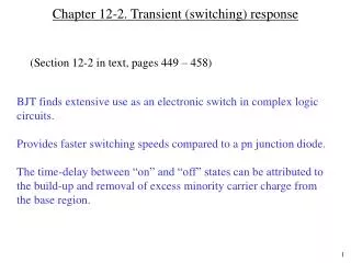
Chapter 12-2. Transient (switching) response. (Section 12-2 in text, pages 449 – 458). BJT finds extensive use as an electronic switch in complex logic circuits. Provides faster switching speeds compared to a pn junction diode.

E N D
Chapter 12-2. Transient (switching) response (Section 12-2 in text, pages 449 – 458) • BJT finds extensive use as an electronic switch in complex logic circuits. • Provides faster switching speeds compared to a pn junction diode. • The time-delay between “on” and “off” states can be attributed to the build-up and removal of excess minority carrier charge from the base region.
Transient response Consider a pnp transistor E B C IE p+ n p IC IB pB(0) QB pB(WB) pB0 xB
Transient response: Base current In the quasi-neutral region of the base, the base lead supplies electrons for: • Recombination with excess holes (= QB/B) • Increasing or decreasing of excess hole charge in base (dQB / dt) • Under steady state, this part is zero (excess hole concentration is equal to excess electron concentration in neutral region) • Injection of electrons to emitter, IEN
Transient response (continued) If we neglect the electrons emitted to the emitter (i.e., = 1) then, where IB and QB are time dependent and = 1. When the transistor is in forward active mode, IE = IB + IC = Holes collected by collector (steady state) Steady-state loss of holes in base by recombination Rate of change of hole conc. in base. Hole current injected from emitter = + + Apply these concepts to turning on a BJT.
S Idealized switching circuits Let us say, base current is suddenly changed from zero to a value IB, by turning on the switch. In the above circuit, the base current changes from zero to VS/RS, if we assume that VS >> VBE, where VBE is the forward voltage drop of emitter-base junction (approx. 0.7 V).
Analysis of switching transients • Using the charge control model we just discussed, we can write, • where IB is constant for t > 0. • Or The general solution of this equation is: assuming the boundary condition that QB(t) = 0 when t = 0 (i.e. starting from “off” state). As QB(t) increases from zero to IBB, the collector current will also increase since the collector current is given by:
Analysis of switching transients (continued) But the collector current cannot increase continuously since IC is limited by the value of RL and VCC. Once, IC reaches VCC / RL, then IC cannot increase even though QB continues to increase. At this value of IC, VCE is close to zero, and C-B junction gets forward biased, and the transistor is said to be in saturation. IC is not equal to dc IB anymore in saturation. for 0 < t < tr for t > tr During 0 < t < tr , the BJT is in active mode. At t = tr , the collector current reaches the maximum value of VCC/RL and does not increase further. The time tr is called turn-on time of the BJT.
Analysis of switching transients (continued) The turn-on timetr can be obtained from: Rearranging and solving for tr: Note that one can reduce the turn-on time by increasing the base current (faster storage charge build up). However, if you make the base current too large, you will be storing too much charge in the base during “on” so that it will affect the turn-off time.
Methods to speed-up turn-off transients • Introduce R-G centers in base. • Use Schottky diode clamp to prevent BJT going into “deep” saturation.
Examples of transient response IB IB t QB t IC t tr