Download
1 / 26
260 likes | 280 Views
This text discusses different network topologies including bus, star, hub/tree, and multi-hop networks, as well as routing techniques such as static and dynamic routing.

E N D
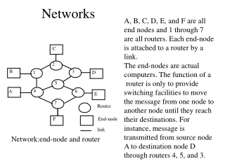
Networks A, B, C, D, E, and F are all end nodes and 1 through 7 are all routers. Each end-node is attached to a router by a link. The end-nodes are actual computers. The function of a router is only to provide switching facilities to move the message from one node to another node until they reach their destinations. For instance, message is transmitted from source node A to destination node D through routers 4, 5, and 3. C 2 B 3 1 D 5 4 A 6 E 7 Router F End-node link Network:end-node and router
Routing Techniques Static routing Routing Dynamic routing Static Routing: In static routing, for a given source, destinations and routes are all predetermined. They are assigned during the design of a network. For instance, node A can send message to node D via 4,5, 3 . Node A can also send message to node D via 1, 2, 3. However, node A cannot send message using the route A 4 1 2 3 D Advantage: easy to design and set-up cost is not high Disadvantage: not very efficient, delay can be very long.
Dynamic Routing Dynamic Routing: In dynamic routing, the routes are calculated when they needed. The routes are not predetermined. Advantages: more efficient, inherently more fault-tolerant. Disadvantages: Set-up cost is high and it is fairly complex to design.
Network Topology: Physical & Logical • The topology of a network defines how the nodes of a network • are connected. • A network is defined by a physical topology and a logical topology. • Physical topology defines how the nodes of the network are • physically connected . • Logical topology defines how the nodes of the network are • physically connected. Dedicated connections between certain selected • source-destination pairs are established using the underlying • physical topology. • In order to have an efficient system, the logical topology should be • chosen such that either the average hop distance or the packet • delay or the maximum flow on any link must be minimal. • Another important issue to select the logical topology is the • simplicity of the routing.
Multi-hop Network 1 w w w 6 w 1, 2 w 4, 1 w 7, w w w 8 1, 7 1 2 Star coupler w T 4 4 2 w w T 3, 5 w w w w T 3, 4 2 7 w w 3 6 w w w w 3 4 5, 6 2, 8 w 5 3 w 8 Physical Topology: 2 X 2 star Logical Topology: 2 X 2 torus
Physical and Logical topologies • Node 1 can directly send information to node 2 and node 3 using frequencies w1 and w2. • For this reason, node 1 is directly logically connected to node 2 and node 3. Although, node 1 is not directly physically connected to node 2 and node 3. • Now, if node 1 wants to send message to node 4, it has to multi-hop through either node 2 or node 3. • For this reason, node 1 is not directly logically connected to node 4. • If node 1 communicates with node 4 via node 2, there will be a wavelength conversion from w1 to w3 at node 2.
Communication Networks Network topologies: • The Bus Network • Hub/Tree Network • Star Network 4 Ring Network
Bus Network • In bus network, all stations are attached to a single cable. • When a station sends a message, it is broadcast down on the cable in both directions. Terminators at the end of the cable prevent the signal from reflecting back to the sender. • All stations on the cable constantly monitor for messages meant to them. When a station detects a message meant for it, it reads the message from the cable and the other stations will ignore it. • Since all stations are sharing the same cable, some form of control is needed to make sure which station will transmit when, otherwise there will be a collision. • Advantages: Easy to wire, quick response, less expensive, and if one station dies, it has no effect on the total network. • Disadvantage: However bad connection to the cable can short it and bring down the entire network.
A bus network topology Use: This topology is useful in LANs. It does not rely on central host.This network can still function if one of the computers malfunctions. Other advantages: easy to wire, quick response, less expensive C 1 C 3 C 2 C 6 C 5 C 4 Problem: The main disadvantage is bad connection to the cable can bring down the entire network. Another problem: collision occurs when 2 nodes send messages simultaneously.
Hub End node Hub Hub Hub Hub A Hub / Tree Network A Hub/Tree Network
Tree Network • In hub or tree network, the wires that are used to connect different nodes are collapsed into a central unit, called hub. • Hub does not perform switching function. • It consists of repeaters that retransmitted all the signals from nodes to all other nodes in the same way. • The multipoint nature of tree topology gives rise to several problems. • The access control is fairly difficult to determine the time slot for each node. Another problem with multipoint is signal balancing. • When two device exchange data over a link, the signal strength of the transmitter should be adjusted. • If it is low, after attenuation, it might not meet the minimum signal strength requirement of the transmitter and minimum signal to noise ratio. If it is very high, it can overload the circuitry of the transmitter resulting in harmonics and other spurious signals.
A ring network topology Use: This topology is useful in LANs. It does not rely on central host.This network can still function if one of the computers malfunctions. C 1 C 6 C 2 Problems: The connecting wire, cable, or optical fiber forms a closed loop. Data are passed along the ring from one computer to another. C 3 C 5 C 4
Ring Network • Ring network consists of nodes that are joined by point-to-point connection to form a closed loop or ring. • The transmitted signal is regenerated at each node. • It is a shared-access network and it has the capability of broadcasting messages. • It needs some form of access control to determine which node will transmit when. • Advantages • The most important advantage of this network is its point-to-point connections. • The electronics and maintenance of point-to-point links are much simpler than multi cast links.
Ring Network • The structure of this network is very simple and it is very easy to insert and delete any number of nodes. • For this reason, ring network is easily scalable and highly modular. • Fault isolation and recovery are much simpler than tree. • Disadvantages: • The disadvantage is it offers only two alternate routes and thereby it can manage only a single fault. • Another important drawback of ring network is its large diameter. • If diameter of a network is high, the number of edges involved in each communication will also be very high resulting in high signal attenuation and network blocking probability.
C 1 C 6 C 2 Host CPU C 3 C 5 C 4 A star network topology Use: This topology is useful for applications where processing must be centralized and some can be performed locally. Problems: All communication pass through the central computer. The communications in the network will stop if the host computer stops functioning.
Star Network • In star network, each station is connected via a point-to-point link to a central point. • This central point is called hub, multi port repeater, or concentrator. • The central point may be “passive”, “active”, or “intelligent”. • A passive hub simply connects the arms of a star, no signal regeneration is performed. • An active hub is like a passive hub, except that it regenerates signals. • Intelligent hubs not only regenerate signals but also perform activities such as intelligent path selection and network management.
Star Network • Advantage: • The main advantage of the star architecture over the bus is its small excess loss, since in case of n-user star the excess loss increases logarithmically with n, while in case of n-user bus it increases linearly with n. • Disadvantage: • Since all information in a star network goes through a central point, stars are easy to troubleshoot.
000 001 100 010 101 011 110 111 Complex Networks: De Bruijn graphs no. of nodes = 2 ^ 3 = 8 Advantages: diameter = max hop no. = 3
Complex Networks:ShuffleNet 0 4 0 1 1 5 2 6 2 3 7 3 A ( 2, 2 ) Shuffle Net.
0,1 0,2 0,3 0,0 1,1 1,2 1,3 1,0 2,0 2,1 2,3 2,2 3,0 3,1 3,2 3,3 A 4 x 4 Manhattan Street Network Complex Networks: Manhattan Street Network
010 011 000 001 111 110 100 101 Complex Networks:Binary Hypercube An 8-node binary hypercube
Fault-tolerant network Fault-tolerant network provides • reliable operation in faulty networks. • alternate ways of communication. Faults in optical networks channel fault link fault node fault
Channel fault • Why and when it occurs? • A channel fault occurs when a single wavelength channel on a link • between two nodes has failed due to the failure of the laser or • receiver for that wavelength channel, or due to cable disconnections. • How to manage? • Thus fault can be managed by routing the traffic to a spare channel • on the same physical link and bypassing the faulty channel.
Link fault • Why and when it occurs? • A link fault occurs due to fiber cut or due to noise • (particularly those running over long distance). • How to manage? • It can be managed by using a bundle of protection fibers in • addition to the working fiber. The performance or survivability • is limited by the number of links in each bundle. • Another way of solving this problem is by providing a • “loopback” mechanism within each node on the same • working fiber.
Node fault • Why and when it occurs? • A node fault occurs due to power outages or catastrophic failure • in an entire WADM node failure. • How to handle? • It is complicated to handle since when this fault occurs, a part of • the conversion capability of the network as a whole is lost and • leaves an open circuit and can result in deadlock of all routing • networks. • One solution is to introduce redundancy in the internal • connections of the networks rather than in the connections of • the nodes. In case of multiple failures, the solution is a “firewall” • that can prevent deadlock spreading in the network. This can be • achieved by a simple device that tomes out if a packet passing • through it stay longer than a specified time.
G G A A F F B E E C C D Survivable route graph B D A Network. Survival route graph.