Download
1 / 26
260 likes | 396 Views
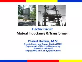
M utual Inductance & Transformer. Electric Circuit. Chairul Hudaya, M.Sc Electric Power and Energy Studies (EPES) Department of Electrical Engineering Universitas Indonesia http://www.ee.ui.ac.id/epes/hudaya. M. i 1. i 2. v 1. v 2. L 1. L 2. Coil 2. Coil 1.

E N D
Mutual Inductance & Transformer Electric Circuit Chairul Hudaya, M.Sc Electric Power and Energy Studies (EPES) Department of Electrical Engineering Universitas Indonesia http://www.ee.ui.ac.id/epes/hudaya
M i1 i2 v1 v2 L1 L2 Coil 2 Coil 1 CIRCUIT WITH MUTUAL INDUCTANCE PASSIVE SIGN CONVENTION : Arrows for I1 and I2 point into plus end of V1 and V2 DOT CONVENTION : If both current reference arrows point into dotted ends or both into undotted ends of inductor, use plus sign for both mutual inductance, otherwise use the minus sign
Dot Convention The dots are placed in such a manner that the currents entering (or leaving) both the dotted terminals will produce adding magnetic flux. In this case the mutual flux linkages will add to the self flux linkages.(Case I) Conversely, if current enters through one dotted terminal and leaves through the other, they produce opposing flux. In this case mutual flux linkages subtract from self linkages.(Case II)
i1 i2 M L1 L2 Coil 2 Coil 1 Case I v1 v2
Case 1: jM + + V1 I1 V2 I2 • • _ _ jL1 jL2 V1 = jL1I1 + jMI2 V2 = jL2I2 + jMI1
i1 i2 M L1 L2 Coil 2 Coil 1 Case II v1 v2
Case 2: jM _ + • I1 V1 V2 I2 • _ + jL2 jL1 V1 = jL1I1 + jMI2 V2 = jL2I2 + jMI1
Example 1: j8 -j4 6 2 • + + I1 I2 va(t) vb(t) j6 j10 _ _ • va(t) = 50cos(400t + 30) V vb = 80cos(400t – 40) V Va = 50300 V Vb = 80-400 V
EXAMPLE 1: Continued j8 -j4 6 2 • + + I1 I2 j10 j6 80-40 V 5030V _ _ • Solve for I1 and I2 Mesh 1 (2 + j10)I1 + j8I2 = 5030 j8I1 + (j6 – j4 + 6)I2 = - 80-40 Mesh 2 (2+j10) j8 I1 5030 = Matrix Form j8 (6+j4) I2 -80-40
Example 2: 8 -j4 j8 j10 • • j3 + j5 12 200 V I1 _ I2 6 Solve for I1 and I2
Example 2: Continued 8 -j4 j8 j10 • • j3 + j5 12 200 V I1 _ I2 6 (8 + j10 + j5 + 6)I1 - (j5 + 6 + j3)I2 = 200 Mesh 1: Mesh 2 -(6 + j5 + j3)I1 + (6 + j5 + j8 – j4 + 12 + j3)I2 = 0 (14+j15) -(6+j8) I1 200 Matrix = -(6+j8) (18+j12) I2 0
BASIC TRANSFORMER From figure V2=ZL.I2 so : Substitute I2 we have :
Simplify Circuit – one loop circuit Reflected impedance ZR
SECONDARY TO PRIMARY RATIO CURRENT RATIO VOLTAGE RATIO
n= N2/N1 called turn ratio of transformer Voltage Ratio Current Ratio
IDEAL TRANSFORMER LAWS Define the primary variables (I1,V1) to satisfy and the secondary variable to violate the passive sign convention. Then if I1 or I2 point into dotted end while the other point into undotted end, use plus sign in both i-v laws, otherwise use minus sign
IMPEDANCE REFLECTED • REFLECTED LOAD INTO PRIMARY
Contoh • Suatu generator menyuplai beban , spesifikasi rating generator tersebut adalah : • V rat = 500 volt S rat = 100 kVA
SISTEM PER-UNIT Besaran yang dijadikan basis utama adalah Daya Semu (S) dan Tegangan (V)
Besarnya I sebenarnyauntuktiap area dapatdiperolehdenganmengalikannilaiI perunitdengannilai I basisnyadi area tersebut