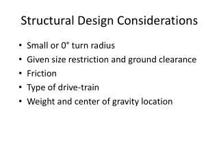
Structural Design Considerations and Airspeeds
260 likes | 618 Views
ITA – Instituto Tecnológico de Aeronáutica. Structural Design Considerations and Airspeeds. Cargas em Aviões. Airspeed Definitions. True Airspeed (ktas) is the true airspeed of the airplane, at the altitude it is flying. Equivalent Airspeed (keas)

Structural Design Considerations and Airspeeds
E N D
Presentation Transcript
ITA – Instituto Tecnológico de Aeronáutica Structural Design Considerations and Airspeeds Cargas em Aviões
Airspeed Definitions • True Airspeed (ktas) • is the true airspeed of the airplane, at the altitude it is flying. • Equivalent Airspeed (keas) • is an airspeed at sea level that would result in the same dynamica pressure experienced by the airplane flying at altitude at its true airspeed. • Indicated Airspeed (kias) • is the airspeed the pilot reads on the airspeed indicator in the cockpit. • Calibrated Airspeed (kcas) • is the Indicated Airspeed plus airspeed correction due to instrument and static source error, which may be a function of flying altitude, Mach number and flap position.
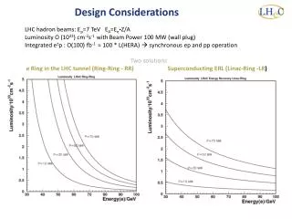
Speed relations Given altitude and Mach number, calibrated airspeed is calculated Given altitude and calibrated airspeed, Mach number is calculated Given calibrated airspeed and Mach number, pressure ratio is calculated Given Mach number and altitude, equivalent airspeed is calculated Given altitude and equivalent airspeed, true airspeed is calculated
Variation of Airspeeds with Altitude 350 kcas True Airspeed at 350 kcas Equivalent Airspeed at 350 kcas
Part 25 § 25.335 – Design airspeeds. The selected design airspeeds are equivalent airspeeds (EAS). Estimated values of VS0 and VS1 must be conservative. (a). Design cruising speed, VC. For VC, the following apply: (1). The minimum value of VC must be sufficiently greater than VB to provide for inadvertent speed increases likely to occur as a result of severe atmospheric turbulence. (2). Except as provided in § 25.335(d)(2), VC may not be less than VB + 1.32 UREF (with UREF as specified in § 25.341(a)(5)(i)). However VC need not exceed the maximum speed in level flight at maximum continuous power for the corresponding altitude. (3). At altitudes where VD is limited by Mach number, VC may be limited to a selected Mach number. (b). Design dive speed, VD. VD must be selected so that VC/MC is not greater than 0.8 VD/MD, or so that the minimum speed margin between VC/MC and VD/MD is the greater of the following values: (1). From an initial condition of stabilized flight at VC/MC, the airplane is upset, flown for 20 seconds along a flight path 7.50 degrees below the initial path, and then pulled up at a load factor of 1.5g (0.5g acceleration increment). The speed increase occurring in this maneuver may be calculated if reliable or conservative aerodynamic data is issued. Power as specified in § 25.175(b)(1)(iv) is assumed until the pullup is initiated, at which time power reduction and the use of pilot controlled drag devices may be assumed; (2). The minimum speed margin must be enough to provide for atmospheric variations (such as horizontal gusts, and penetration of jet streams and cold fronts) and for instrument errors and airframe production variations. These factors may be considered on a probability basis. The margin at altitude where MC is limited by compressibility effects must not be less than 0.07M unless a lower margin is determined using a rational analysis that includes the effects of anyautomatic systems. In any case, the margin may not be reduced to less than 0.05M.
Part 25 § 25.335 – Design airspeeds. (c). Design maneuvering speed, VA. For VA, the following apply: (1). VA may not be less than where n is the limit positive maneuvering load factor at VC; and VS1 is the stalling speed with flaps retracted. (2). VA and VS1 must be evaluated at the design weight and altitude under consideration. (3). VA need not be more than VC or the speed at which the positive CNmax curve intersects the positive maneuver load factor line, whichever is less. (d). Design speed for maximum gust intensity, VB. (1). VB may not be less than where: Kg = gust alleviation factor = mg = airplane mass ratio = VS1 = the 1-g stalling speed based on CNmax with the flaps retracted at the particular weight under consideration; VC = design cruise speed (knots equivalent airspeed); Uref = the reference gust velocity (feet per second equivalent airspeed) from § 25.341(a)(5)(i); w = average wing loading (pounds per square foot) at the particular weight under consideration. r = density of air (slug/ft3); c = mean geometric chord of the wing (feet); g = acceleration due to gravity (ft/sec2); a = slope of the airplane normal force coefficient curve, CNA per radian; (2). At altitudes where VC is limited by Mach number-- (i). VB may be chosen to provide an optimum margin between low and high speed buffet boundaries; and, (ii). VB need not be greater than VC.
Part 25 § 25.335 – Design airspeeds. (e). Design flap speeds, VF. For VF, the following apply: (1). The design flap speed for each flap position (established in accordance with § 25.697(a)) must be sufficiently greater than the operating speed recommended for the corresponding stage of flight (including balked landings) to allow for probable variations in control of airspeed and for transition from one flap position to another. (2). If an automatic flap positioning or load limiting device is used, the speeds and corresponding flap positions programmed or allowed by the device may be used. (3). VF may not be less than- (i). 1.6 VS1, with the flaps in takeoff position at maximum takeoff weight; (ii). 1.8 VS1, with the flaps in approach position at maximum landing weight; and (iii). 1.8 VS0 with the flaps in landing position at maximum landing weight. (f). Design drag device speeds, VDD. The selected design speed for each drag device must be sufficiently greater than the speed recommended for the operation of the device to allow for probable variations in speed control. For drag devices intended for use in high speed descents, VDD may not be less than VD. When an automatic drag device positioning or load limiting means is used, the speeds and corresponding drag device positions programmed or allowed by the automatic means must be used for design. § 25.341 -- Gust and turbulence loads. (5). The following reference gust velocities apply: (i). At the airplane design speed VC: Positive and negative gusts with reference gust velocities of 56.0 ft/sec EAS must be considered at sea level. The reference gust velocity may be reduced linearly from 56.0 ft/sec EAS at sea level to 44.0 ft/sec EAS at 15000 feet. The reference gust velocity may be further reduced linearly from 44.0 ft/sec EAS at 15000 feet to 26.0 ft/sec EAS at 50000 feet.
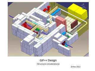
M = 0,92 M = 0,85 340 kcas 425 kcas VC and VD profiles Low altitudes: VC = 340 kcas (chosen) VD = VC/0,8 = 425 kcas (calculated) High altitudes: MC = 0,85 (chosen) MD = MC + 0,07 = 0,92 (calculated)
Maneuvering speed VA The maneuvering speed VA is the maximum airspeed at which the pilot may apply a single application of any one control surface to its maximum angle, limited by 300 lb of pilot effort, stops or blowdown. This control surface motion is intended to be in one direction only and does not include oscillatory inputs. (1). VA may not be less than where n is the limit positive maneuvering load factor at VC; and VS1 is the stalling speed with flaps retracted. (2). VA and VS1 must be evaluated at the design weight and altitude under consideration. (3). VA need not be more than VC or the speed at which the positive CNmax curve intersects the positive maneuver load factor line, whichever is less. Flaps Up Buffet Limited
Maneuvering speed VA Flaps Up Buffet Limited
Design speed for maximum gust intensity VB (1). VB may not be less than where ... (2). At altitudes where VC is limited by Mach number-- (i). VB may be chosen to provide an optimum margin between low and high speed buffet boundaries; and, (ii). VB need not be greater than VC.
Design cruising speed VC (a). Design cruising speed, VC. For VC, the following apply: (1). The minimum value of VC must be sufficiently greater than VB to provide for inadvertent speed increases likely to occur as a result of severe atmospheric turbulence. (2). Except as provided in § 25.335(d)(2), VC may not be less than VB + 1.32 UREF (with UREF as specified in § 25.341(a)(5)(i)). However VC need not exceed the maximum speed in level flight at maximum continuous power for the corresponding altitude. (3). At altitudes where VD is limited by Mach number, VC may be limited to a selected Mach number.
Design dive speed VD VD must be selected so that Vc/Mc is not greater than 0.8 VD/MD, or so that the minimum speed margin between VC/MC and VD/MD is the greater of the following values: (1). From an initial condition of stabilized flight at VC/MC, the airplane is upset, flown for 20 seconds along a flight path 7.50 degrees below the initial path, and then pulled up at a load factor of 1.5g (0.5g acceleration increment). The speed increase occurring in this maneuver may be calculated if reliable or conservative aerodynamic data is issued. Power as specified in § 25.175(b)(1)(iv) is assumed until the pullup is initiated, at which time power reduction and the use of pilot controlled drag devices may be assumed; (2). The minimum speed margin must be enough to provide for atmospheric variations (such as horizontal gusts, and penetration of jet streams and cold fronts) and for instrument errors and airframe production variations. These factors may be considered on a probability basis. The margin at altitude where MC is limited by compressibility effects must not be less than 0.07M unless a lower margin is determined using a rational analysis that includes the effects of any automatic systems. In any case, the margin may not be reduced to less than 0.05M.
M = 0,92 M = 0,85 340 kcas 425 kcas Design dive speed VD
Maneuvering envelopes VA MA
Design flap speeds VF For VF, the following apply: (1). The design flap speed for each flap position (established in accordance with § 25.697(a)) must be sufficiently greater than the operating speed recommended for the corresponding stage of flight (including balked landings) to allow for probable variations in control of airspeed and for transition from one flap position to another. (2). If an automatic flap positioning or load limiting device is used, the speeds and corresponding flap positions programmed or allowed by the device may be used. (3). VF may not be less than- (i). 1.6 VS, with the flaps in takeoff position at maximum takeoff weight; (ii). 1.8 VS, with the flaps in approach position at maximum landing weight; and (iii). 1.8 VS with the flaps in landing position at maximum landing weight. VS = stall speed at the flap position, design weight and power/landing gear configurations under consideration.
Maneuvering envelopes with flaps down (FAR § 25.345) (a). If wing flaps are to be used during takeoff, approach, or landing, at the design flap speeds established for these stages of flight under § 25.335(e) and with the wing flaps in the corresponding positions, the airplane is assumed to be subjected to symmetrical maneuvers and gusts. The resulting limit loads must correspond to the conditions determined as follows: (1). Maneuvering to a positive limit load factor of 2.0; and (2). Positive and negative gusts of 25 ft/sec EAS acting normal to the flight path in level flight. Gust loads resulting on each part of the structure must be determined by rational analysis. The analysis must take into account the unsteady aerodynamic characteristics and rigid body motions of the aircraft. The shape of the gust must be as described in § 25.341(a)(2) except that- Uds = 25 ft/sec EAS; H = 12.5 c; and c = mean geometric chord of the wing (feet). (b). The airplane must be designed for the conditions prescribed in paragraph (a) of this section, except that the airplane load factor need not exceed 1.0, taking into account, as separate conditions, the effects of- (1). Propeller slipstream corresponding to maximum continuous power at the design flap speeds VF, and with takeoff power at not less than 1.4 times the stalling speed for the particular flap position and associated maximum weight; and (2). A head-on gust of 25 feet per second velocity (EAS). (c). If flaps or other high lift devices are to be used in en route conditions, and with flaps in the appropriate position at speeds up to the flap design speed chosen for these conditions, the airplane is assumed to be subjected to symmetrical maneuvers and gusts within the range determined by- (1). Maneuvering to a positive limit load factor as prescribed in §25.337(b); and (2). The discrete vertical gust criteria in § 25.341(a). (d). The airplane must be designed for a maneuvering load factor of 1.5 g at the maximum takeoff weight with the wing-flaps and similar high lift devices in the landing configurations.
Maneuvering envelopes with flaps down (FAR § 25.345) Flaps down at takeoff and landing weights MlW F30 MTOW F1 Landing flaps at takeoff weight MTOW F30