Structural Design Considerations for Chassis and Drive-Train with Zero Turn Radius
This document outlines critical structural design considerations for creating a chassis and drive-train system with a small or zero-degree turn radius. Key factors include wheel size, weight distribution, and center of gravity, which help determine the chassis dimensions. The design considers multi-directional wheels, suitable friction materials, and effective steering mechanisms. An octagonal chassis made of aluminum is proposed, incorporating two decks and modified servos for movement. Potential structural issues like stress on servo shafts, vibration, and design flexibility are also discussed.


Structural Design Considerations for Chassis and Drive-Train with Zero Turn Radius
E N D
Presentation Transcript
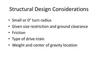
Structural Design Considerations • Small or 0° turn radius • Given size restriction and ground clearance • Friction • Type of drive-train • Weight and center of gravity location
Wheels • First considered to determine range of chassis size to work with • Quantity and type which help with finalizing drive-train • Explored track style, multi-directional and standard hobbyist rubber wheels • Size to provide enough ground clearance
Chassis and Drive-train • Shapes and sizes • Square, triangular and rectangular • Material • Lightweight and easy to machine • Deck quantity • Quantity, speed and torque of motors • Steering mechanism
Wheels-Current Design • Multi-directional • Rubber coated to provide enough friction • (4) 4” diameter wheels • Assembled 90° apart • Provides 0° turn radius
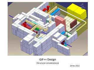
Chassis and Drive-train/Current Design • Octagonal shape keeping wheels 90° apart • Aluminum chassis • Two decks • Four modified servos to drive • No steering required
Possible Structural Issues • Amount of stress on shaft of servos • Possibly perform FEA to determine max stress • Clearance with face of wheels • Approach carpet/ramps at different angle • Change wheels (last resort) • Vibration • Change thickness or material of chassis for more flexibility • Shock absorption on wheel (last resort)