Download
1 / 28
280 likes | 398 Views
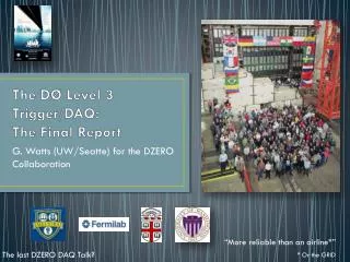
The DØ Level 3 Trigger/DAQ: The Final Report. G. Watts (UW/ Seatte ) for the DZERO Collaboration. “More reliable than an airline*”. The last DZERO DAQ Talk?. * Or the GRID. Overview of DØ Trigger/DAQ. Standard Tiered HEP DAQ/Trigger Design Readout at 1 kHz is about 300 MB/sec

E N D
The DØ Level 3 Trigger/DAQ:The Final Report G. Watts (UW/Seatte) for the DZERO Collaboration “More reliable than an airline*” The last DZERO DAQ Talk? * Or the GRID
Overview of DØ Trigger/DAQ Standard Tiered HEP DAQ/Trigger Design Readout at 1 kHz is about 300 MB/sec Data rate out of the Trigger farm is 60 MB/sec 1.7 MHz Level 1 Fast, course resolution, readout 2 kHz Firmware Trigger Algorithms Level 2 Software Trigger Algorithms Specialized Hardware 1 kHz Commodity Hardware DAQ Full Readout Occurs L3 Trigger Farm G. Watts (UW/Seattle) 200 Hz
DZERO DAQ Data Flow Topology ROC ROC ROC ROC ROC A standard scatter-gather architecture L3 Node L3 Node L3 Node L3 Node L3 Node ROC – VME based Read out Crate with a Single Board Computer L3 Node – Commodity Linux multicore computer Large CISCO switch… About 20m distant Electrically isolated G. Watts (UW/Seattle)
Performance Factors Throughout the Run Tevatron Increases Luminosity Architecture lasted 10 years! Physicists Get Clever • Trigger software written by large collection of non-realtime programmer physicists. • CPU time/event has more than tripled. • Continuous upgrades since operation started • Have added about 10 new crates since the start • Started with 90 nodes, ended with almost 200, peak was about 330, all have been replaced • Single core at start, last purchase was dual 4-core. • No major unplanned outages # of Multiple Interactions Increase Trigger List Changes Increased Noise Hits More CPU Time Per Event Rejection Moves to L1/L2 Increased Data Size Trigger HW Improvements G. Watts (UW/Seattle)
24/7 from March 2001 to September 30, 2011 Constant pressure: L3 deadtime shows up in this gap! G. Watts (UW/Seattle)
Papers! Previous VAX/VMS based DAQ system This DAQ System! 10,347,683 K events served!! An overwhelming success G. Watts (UW/Seattle)
Design & Construction G. Watts (UW/Seattle)
Philosophy Data Flow Configuratoin Unidirectional Directed (destination known) Buffered at origin and destination Not buffered while in flight Minimize copying of data Automatic Configuration. Configuration at boot time. Auto-reconfiguration when hardware changes. Extensive monitoring system with minimal impact on running. Flow Control 100% TCP/IP! Small messages bundled to decrease network overhead Messages compressed via pre-computed lookup tables G. Watts (UW/Seattle)
Hardware The Read Out Crate • VME based crates • All DZERO readout ends here • Interface between detector and DAQ • One slot has SBC • VMIC 7750’s, PIII, 933 MHz • 128 MB Ram • Universe II chip • Dual 100 MB Ethernet • 1 or 2 used depending on data load • 4 upgraded to GB late in run to deal with increased occupancy • SBC has custom built extension • Control lines on J3 backplane that trigger readout • Readout starts when detector control signals there is an event ready. Home brew device driver (Fermi CD) for efficient VME readout G. Watts (UW/Seattle)
Hardware CISCO 6590 switch • 16 Gb/s backplane • 9 module slots, all full • 8 port GB • 112 MB shared output buffer per 48 ports • Not enough to do full event buffering • Connection between SBCs and switch optically isolated • Static configuration, maintained by Fermilab Computing Division Farm Nodes n-core 1U AMD’s and Xeon’s with varying amounts of memory 1 Trigger Process per core Single 100 Mb Ethernet connection Peaked around 330 1U boxes, but later in run was smaller number with faster CPU’s 1 local disk (which failed rarely) Fans (which failed a lot) G. Watts (UW/Seattle)
Data Flow 1 A Level 2 Trigger fires, and an accept message is sent to the DAQ Routing Master as well as the detector readout control by the Trigger Framework SBC in ROC Farm Node The Routing Master is the point of entry into the DAQ system A single SBC, sitting in a special crate with an interface to the Trigger Framework. L2 Accept message contains an event number and a 128 bit trigger mask SBC in ROC Farm Node SBC in ROC Farm Node Readout crates start pushing data to their SBC’s Data is buffered in the SBC’s. SBC makes the data uniform SBC in ROC Routing Master SBC in ROC L2 Accept DØ Trigger Framework VME G. Watts (UW/Seattle)
Data Flow 2 Routing Master decides what node should build and run the Level 3 Trigger code for the event. This information is sent to all SBC’s and the Node.. SBC in ROC Farm Node • Node decision is based on the trigger bit mask and cached configuration information • Nodes busy fraction is also taken into account, using a token counting system • This properly accounts for node’s processing ability. • 10 decisions are accumulated before nodes and SBCs are notified. SBC in ROC Farm Node SBC in ROC Farm Node SBC in ROC Routing Master ROC SBC in ROC DØ Trigger Framework G. Watts (UW/Seattle)
Data Flow 3 The SBC’s send their data fragments to the Farm Nodes. SBC in ROC Once all the event fragments have arrived a token is sent back to the Routing Master as long as the node has room to accept another event. Farm Node SBC in ROC Farm Node SBC in ROC Farm Node SBC in ROC Routing Master SBC in ROC DØ Trigger Framework G. Watts (UW/Seattle)
Data Flow 4 The Node builds the event, runs the trigger on the event, and if it passes, sends it off to the online system. SBC in ROC The event fragments are built into the official RAW event chunk in shared memory (which was designed to do this without copying in this case). The Trigger process (~ 1 per core) can only read from this shared memory Trigger result chunk is returned, and sent to the online system. Farm Node SBC in ROC Farm Node SBC in ROC Farm Node SBC in ROC Routing Master SBC in ROC DØ Trigger Framework G. Watts (UW/Seattle)
Flow Control & Back Pressure SBC in ROC If there is no room in the SBC’s internal buffers it will refuse to read out the crate Quickly causes DAQ to stop with a “front-end busy” status. If the farm node can’t send an event to the online system, its internal buffers will fill It will refuse to receive the SBC’s data. Many minutes of buffer space in the farm! Farm Node If the # of tokens for free nodes gets too low, the Routing Master will disable the triggers in the Trigger Framework Routing Master VME DØ Trigger Framework G. Watts (UW/Seattle)
Configuration G. Watts (UW/Seattle)
Configuration Basics This is not a no-single-point-of-failure system • Spent extra money on that hardware • Out of about 70 SBCs, only 5 failed in 10 years, and 2 of those were due to user error. Also had spares on hand. • CISCO switch never hic-uped and we bought more capacity than we required. DZERO made the policy decision that all crates are required – so each read out crate becomes a single point of failure. The Routine Master and networking infrastructure are single points of failure Some of the configuration machines are single points of failure The Nodes are not. Failed a lot… Mostly fans, some disks And then there was the software… G. Watts (UW/Seattle)
Some Timings Start Configure – 26 sec Start Run #nnnnn – 1 sec Configured Running Unconfigure – 4 secs Stop Run #nnnnn – 1 sec Pause 1 sec Resume 1 sec Paused G. Watts (UW/Seattle)
Protecting Against Crashes Over the course of the 10 years we had the full class of software related crashes In Linux - slow downs or hard crashes. In our custom kernel driver for efficient VME readout In our user level code that was part of the DAQ Our strategy for the configuration turned out to be immensely helpful here Hard reset any machine and when it finished booting it should come back into the DAQ without any shifter intervention. Endeavor to support this with minimal interruption of data flow. This strategy helped keep L3/DAQ’s dead time to less than a few minutes per week G. Watts (UW/Seattle)
Performance G. Watts (UW/Seattle)
Hardware Performance Single Board Computer Farm Nodes • Most expensive single item in system (besides switch) • Most reliable – went out of production! • Replaced less than one per year • User error often at fault • Reduced version of Linux • Updates sometimes required due to Fermilab security policies • Code not modified in last 7 years of the experiment • Problems: • Large number of TCP/IP connections caused Linux intermittent flakiness. • TFW 16 bit run number roll over in coincidence with another problem caused trouble. • Standard rack-mount servers. Cheap. Too cheap sometimes. • Managed jointly with the Fermilab CD who have a lot of experience with farms. • Problems: • Reliability issues: 1/month required warrantee service. • Quality was a function of purchase batch • Modified bidding to account for this. • Computers coming back from service had to be cleaned of old versions of the trigger • Special hacks for partitions with 1 node • Did have to debug linux kernel driver… G. Watts (UW/Seattle)
Single Board Computers At 1 kHz CPU is about 80% busy Data transfer is VME block transfer (DMA) via the Universe II module G. Watts (UW/Seattle)
FarmNodes • Different behavior vs Luminosity • Dual Core seems to do better at high luminosity • More modern systems with better memory bandwidth CPU Time Per Event G. Watts (UW/Seattle)
Event Buffering SBC Buffering • Event fragments are buffered until the RM sends a decision • RM buffers up to 10 decisions before sending them out • We’ve never had a SBC queue overflow Farm Node Buffering • RM bases node event decision on size of internal queue • Provides a large amount of buffering space • Automatically accounts for node speed differences without having to make measurements • The occasional infinite loop does not cause one node to accumulate an unusually large number of events. Cisco Switch Buffering Drops buffers when it can’t send RM tokens means we never saw this unless some other problem has occurred G. Watts (UW/Seattle)
Future & Conclusions G. Watts (UW/Seattle)
Upgrades G. Watts (UW/Seattle)
Conclusion G. Watts (UW/Seattle) • This DØ DAQ/L3 Trigger has taken every single physics event for DØ since it started taking data in 2002. • > 10 billion physics events • Calibration runs • Test runs, etc. • 63 VME sources powered by Single Board Computers sending data to ~200 off-the-shelf commodity CPUs at the end of the run. • Data flow architecture is push, and is crash and glitch resistant. • Has survived all the hardware, trigger, and luminosity upgrades smoothly • Upgraded farm size from 90 to ~330 and back to 200 nodes with no major change in architecture. • Evolved control architecture means minimal dead time incurred during normal operations • Primary responsibility is carried out by 3 people (who also work on physics analysis) • This works only because Fermi Computing Division takes care of the farm nodes...
A subset of people that worked on L3 that were able to gather for the Tevatron End-Of-Run-Party G. Watts (UW/Seattle)