FIRE SPRINKLER FUNCTIONALITY AND INSTALLATION.docx
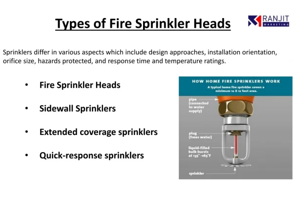
Fire sprinkler heads are components of a fire sprinkler system that discharges water when the fire has been detected. They come in assorted designs, with conventional heads discharged onto the ceiling, upright or pendant spray sprinklers aim all the water straight down, and side wall sprinklers attach to a high point on the wall

FIRE SPRINKLER FUNCTIONALITY AND INSTALLATION.docx
E N D
Presentation Transcript
FIRE SPRINKLER FUNCTIONALITY AND INSTALLATION INTRODUCTION: Fire sprinkler heads are components of a fire sprinkler system that discharges water when the fire has been detected. They come in assorted designs, with conventional heads discharged onto the ceiling, upright or pendant spray sprinklers aim all the water straight down, and side wall sprinklers attach to a high point on the wall. The plug inside the head that holds back the water may be made of Wood’s metal, a mixture of bismuth, lead, tin, and cadmium, or a small glass bulb containing a glycerin-based liquid. Sprinklers use far less water than fire hoses and should only be installed by a company certified by a reputable body. Question #1 – Test Header Height A building with a fire pump will include a test header located on the exterior of a building. Does NFPA 20 (2013) require a specific minimum and maximum height for the test header? No, the test header or hose valves are not required to have a minimum or maximum height according to NFPA 20. A test header must be built on an outer wall or in another location outside the pump room that permits water release during testing, according to NFPA 20, 2013 edition, Section 4.20.1.4. There is no minimum or maximum installation height specified in Section 4.20.3.3 for hose valve placements. The NFPA 2022 edition of this still applies. The hose valves must be outside, in a secure area, and capable of thoroughly testing the fire pump in order to comply with the standard's requirements. The hose valves must be operated and the hose connected with sufficient clearance. Access and installation height are not as crucial as they are for fire department connections because the test header is utilized for testing rather than emergency operations. The most typical installation height is 18 in. to 48 in. above finished grade, in accordance with NFPA 13, 2013 edition, Section A.8.17.2 for the fire department connection. It is typically better to be on the lower end of this height range with the fire pump test header to make connecting the hose easier.
Question #2 – Live/Work Area and Sprinkler Protection Does an R-2 Live/Work unit in accordance with the International Building Code consisting of a single dwelling over a small office require a sprinkler system? According to Section 903.2.8 of the IBC, live/work units must be protected by an automatic sprinkler system. Section 508.5.7 of the IBC's 2021 edition contains this provision. There are no exceptions to the fire sprinkler requirement because Section 903.2.8 stipulates that all occupancies with a Group R fire area must have an automated sprinkler system. By state or local amendment, certain jurisdictions have changed the Group R sprinkler regulations. The only situation in which sprinkler protection might be excluded is this one. Question #3 – Geothermal Water Tank A project’s primary water source is to be a geothermal water storage tank with water heated to 108-degrees Fahrenheit. This supply has been accepted by the AHJ as an acceptable water source. Will this hot water be an issue with the fire sprinklers? C Question #4 – Including Friction Loss for Valves Larger Than 2 Inches in Calculations
Based upon Section 23.4.4.8.1 (1) of the 2016 edition of NFPA 13, can the friction loss for valves larger than 2 inches be ignored when performing hydraulic calculations? No, when performing hydraulic calculations on piping bigger than 2 inches, you cannot disregard pipe fittings and devices. In line with Section 23.4.4.8.1, "Pipe friction loss shall be calculated in accordance with the Hazen-Williams formula using C values from Table 23.4.4.8.1 as follows:" ● Elevation variations that effect sprinkler discharge must be estimated. This includes pipe, fittings, and devices such valves, metres, flow switches in pipes 2 inches in diameter or less, and strainers. According to the way it is written, the "2 inches or less in size" clause only applies to the flow switch-related device within that comma segment. Therefore, flow switches in pipes bigger than 2 inches do not need to be factored into the calculation. However, regardless of pipe size, all other fittings and devices must be factored into the hydraulic calculations as an equivalent length. Question #5 - Distance from Hose Stations in Parking Floors Based upon the 2013 edition of NFPA 14, in a parking lot, should the distance to hose connections be calculated based on the walking distance outside parking spots or it is permitted to calculate the distance based on running hoses across parking spaces? NFPA 14, Standard for the Installation of Standpipe and Hose Systems, 2013 version, does not offer any instructions on how trip distance is calculated. However, the technical committee has provided some direction going ahead by defining the phrase "travel distance" in the future 2023 edition of the standard. The revised phrasing (in section 3.3.33) indicates an intention to include barriers in the calculation of journey distance and to require that it be based on a natural walking path circumnavigating automobiles. The "natural path of travel" is referred to as the "travel distance" in this section, and it is stated that the travel distance is measured "curving around any corners or obstructions." Question #6 - Standpipe Drain Risers In accordance with the 2016 edition of NFPA 14, when is a drain riser required and what are the requirements for this drain?
Only when standpipe pressure-regulating valves (PRVs) are installed is a drain riser necessary. The drain riser must be placed next to each standpipe when PRVs are put on standpipes, and it must have a connection point for testing on at least every other floor. The connection needs to have a 2 12 inch valve and a 3 inch drain in order to be proportioned for the discharge in compliance with Section 7.11.1. Standpipes without pressure-regulating valves (standard hose valves) are simply required to have a system main drain; drain risers are not necessary. The main drain has to be set up or conform to Section 7.11.2's specifications. In Section 7.11.1.3 of the standard, there are size specifications for drains employing common pipe. The common plumbing must be sized for the combined flow when drain risers are linked and run to a single discharge point. In acceptance testing, several drains are frequently used, however drain sizing and the area of water output must be taken into account. Question #7 – Water Shields for Sidewall Sprinklers Based on special FPE/AHJ requirements, water shields are required for the sidewall sprinkler installed beneath the car levels of a car stacker. Are there listed water shields for sidewall sprinklers and if not are there any requirements for the size, location, and orientation of water shields in the 2016 edition of NFPA 13? To our knowledge, there are no listed water shields for sidewall sprinklers; however, it may be prudent to check with the sprinkler manufacturer. There is, however, guidance in NFPA 13. NFPA
13 does recognize the use of water shields other than intermediate level rack sprinklers. For example, Section 8.5.5.3.4 states that sprinklers under open gratings must be intermediate level or “otherwise shielded from the discharge of overhead sprinklers.” The annex to this section also suggests: ● Water shields over automatic sprinklers should be “not be less, in least dimension, than four times the distance between the shield and fusible element…”. As this requirement is not specific to the situation described and is likely addressing upright sprinklers. It is suggested that the specifics of the water shield be discussed with the project engineer and the AHJ. It must also be noted that while it is a requirement that sprinkler guards be listed (see 6.2.8) there is no specific requirement for “water shields” to be listed. However, care should be taken to ensure that any “water shield” used does not disrupt the spray pattern of the sprinklers and is sufficient to serve the intended purpose. Again, it is suggested that the specifics of the water shield be discussed with the project engineer and the AHJ and possibly the sprinkler manufacturer. Finally, it needs to be noted that “heat collectors” are not permitted to be used to assist in the activation of a sprinkler. (See 8.5.4.1.4.) Question #8 – ESFR Skylights The project consists of a storage facility equipped with pendent 25.2K ESFR sprinklers. The structure has multiple skylights, which are 35 square feet in area and 2 feet 9 inches deep. How are these to be addressed in the 2019 edition of NFPA 13? The allowance to exclude sprinklers per section 9.3.16 would not apply because the in question skylights are larger than 32 square feet. Furthermore, because the skylights are 2 feet 9 inches deep and K-25.2 ESFR sprinklers must be installed between 6 and 18 inches below the ceiling, it is impossible to install sprinklers in a position that would protect both the ceiling and the skylights. This suggests that there are two choices: 1. Increase the sprinklers in each skylight. Note that the sprinkler protecting the skylight must be an intermediate temperature sprinkler in accordance with Section 9.4.2.5 (4) and Table 9.4.2.5(b). 2. Installing a sheet of glass or another transparent material at the base of the skylight to cover the depression is another option if the recessed region is indeed a skylight and not a heat vent. This would make the skylight a noncombustible concealed space that doesn't need sprinklers, allowing the heat from the fire to reach the sprinkler without an additional delay, equivalent to any smooth flat ceiling.
It should be noted that Section 9.2.17.1 specifies that a skylight (of any size) that permits venting must be protected if it opens. Additionally, since this is probably a storage facility, the rules of Sections 20.6.6.2 and 20.6.6.3 would apply if the skylights were deemed roof heat or smoke vents. Question #9 – Small Hose Connections in Storage Occupancy Section 8.17.5.1.3(2) in the 2013 edition of NFPA 13 states that hose connections can be supplied from separate piping system for small hose connections. Should this be a separate sprinkler zone, or is it acceptable to connect this piping after the flow switch of the sprinkler system? This is storage occupancy with only one sprinkler zone. Small hose connections must be made using a separate pipe system, according to NFPA 13, 2013 edition, Section 8.17.5.1.3(2). The handbook commentary for Section 8.17.5.1.1 states, "When specifically required, the hose connections can be supplied from separate or adjacent systems or outside hydrants, so that the ceiling sprinklers can be shut off during the clean-up operation." This requirement's intention is reflected in this statement. The small hose connections may be served by a separate pipe system in this instance because there is just one sprinkler system present. The overhead sprinkler system can be turned off during the cleanup operation without affecting the small hose connections because of the connection of the separate piping system that serves the small hose valves to the sprinkler system. The standard exempts small hose connections from having to be hydraulically engineered to deliver a particular flow and/or pressure. There are no minimum flow or pressure restrictions for small hose connections because they are only meant for mopping up activities and not for use in fire departments or firefighting. Although it should be noted that Section 11.1.6.3 does call for an inside hose allowance to be included for inside hose connections (50 gpm for a single hose connection and 100 gpm for multiple hose connections), this requirement is not absolute. Small hose connections must be made using a separate pipe system, according to NFPA 13, 2013 edition, Section 8.17.5.1.3(2). The handbook commentary for Section 8.17.5.1.1 states, "When specifically required, the hose connections can be supplied from separate or adjacent systems or outside hydrants, so that the ceiling sprinklers can be shut off during the clean-up operation." This requirement's intention is reflected in this statement. The small hose connections may be served by a separate pipe system in this instance because there is just one sprinkler system present. The overhead sprinkler system can be turned off during the cleanup operation without affecting the small hose connections because of the connection of the separate piping system that serves the small hose valves to the sprinkler system. The standard exempts small hose connections from having to be hydraulically engineered to deliver a particular flow and/or pressure. There are no minimum flow or pressure restrictions for small hose connections because they are only meant for mopping up activities and not for use in fire departments or firefighting. Although it should be noted that Section 11.1.6.3 does call for an inside hose allowance to be included for inside hose connections (50 gpm for a single hose connection and 100 gpm for multiple hose connections), this requirement is not absolute.
The specifications for sizing pipe serving small hose connections are found in Section 8.17.5.1.4. All piping may be 1 12 inches in diameter, as stated in Section 8.17.5.1.4(3). Question #10 – Floor Control Valve for Parking Level Dry System A project consists of a large three-story apartment building plus one underground level of parking. The total area of all floors combined exceeds 52,000 square feet. A sprinkler system is to be provided in accordance with the 2013 edition of NFPA 13. The system will consist of a wet pipe system on the occupied floors and a dry system in the attic (fed from a dry pipe valve on the 3rd floor) and the parking level. Section 8.16.1.5 requires a floor control valve assembly on each floor. Section 8.16.1.5.2 allows the attic level to be supplied from the 3rd floor level. Is it allowed to run a dry supply from the 3rd floor dry valve to feed the dry system at the parking level or would it need to have its own control valve located on the same level per NFPA 13 (2013 edition) 8.16.1.5.1? Yes, but the AHJ could need to give their approval in this case. With two exceptions, the 2013 edition just stipulates that a floor control valve assembly must be installed on each floor. When the total area of all floors combined does not exceed the system area constraints mentioned in Section 8.2.1, a floor control valve assembly on the floor below may be used to supply the top level of the building. Floor control valve assemblies are not necessary in these cases. The 2016 edition of NFPA 13 introduced two revisions to this regulation that might help with the problem mentioned. It should be noted that in the 2016 edition of NFPA 13, the requirements that were included in Section 8.16.1.5 in the 2013 edition were shifted to Section 8.2.4. The phrase "for each individual floor level" was substituted with "on each floor level" in the 2016 edition, which amended the requirement that floor control valve assemblies be present "on each floor level." With this modification, it is now possible to place the necessary floor control valve components on a level apart from the one being served. Sometimes it makes more sense to place all of the sprinkler components in one area, such as a riser room or similar place far from the floor being served. This part had another amendment to remove the necessity for floor control valves on each level for dry systems in parking garages. The challenge of securing unheated parking garages with a single dry-pipe valve and then installing separate floor control valves downstream is acknowledged by this adjustment.
Question #11 – Pressure Relief Valve Requirement for Diesel Fire Pump A diesel pump (without a pressure limiting driver) rated for 60 psi will have 67.5 psi churn with maximum suction pressure of 56 psi. Components are rated for 175 psi. As 121% of churn pressure (81.68 psi) + suction pressure = only 138 psi, does NFPA 20 require, or would there be any advantage to installing a pressure relief valve? No, the standard does not mandate the use of a relief valve. A pressure relief valve is needed for diesel fire pumps, according to NFPA 20, 2013 edition, Section 4.18.1.2, "where a total of 121 percent of the net rated shutoff (churn) pressure plus the maximum static suction pressure, adjusted for elevation, exceeds the pressure for which the system components are rated." As was noticed in your situation, the maximum system operating pressure of 175 psi is not exceeded by 121% of net pressure plus maximum suction pressure; hence a relief valve is not required by the standard. Pressure relief valves must only be used when specifically approved by this standard, according to Section 4.18.1.1. The goal of the standard is to only use a relief valve when absolutely necessary to avoid system over pressurization in the case that the engine speed is out of whack. Unless it is conceivable for the fire pump churn pressure to approach or surpass the maximum system working pressure, providing a relief value would not be advantageous. Without a significant change to the city water supply to the pump (over a 35 pressure increase), that is not feasible in this situation. Question #12 – Cantilever Hanger A project includes a unique hanger style (cantilever hanger). Is there a way to calculate this hangar style as a reviewer, or is this something that needs to be certified by a structural engineer? Any hanger that is not prescriptively specified in Chapter 9 of the 2016 edition of NFPA 13 is not allowed until a registered professional engineer (PE) certifies that the requirements of Section 9.1.1.2, conditions 1 through 5, are satisfied. The decision of whether a performance-based hanger assembly conforms with NFPA 13 is not the responsibility of the plan reviewer. The project engineer must provide proof that all the requirements in Section 9.1.1.2 have been met, which must be signed by a registered PE.
A unique hanger style (cantilever hanger). Is there a way to calculate this hangar style as a reviewer, or is this something that needs to be certified by a structural engineer? project includes a