Download
1 / 13
140 likes | 319 Views
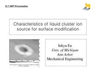
11.7.2007 Presentation. Characteristics of liquid cluster ion source for surface modification. Inkyu Eu Univ. of Michigan Ann Arbor Mechanical Engineering. 1.Liquid cluster ions 2.Etching characteristics of liquid cluster ion 3.Comparisons of the yield between ion and cluster ion

E N D
11.7.2007 Presentation Characteristics of liquid cluster ion source for surface modification Inkyu Eu Univ. of Michigan Ann Arbor Mechanical Engineering
1.Liquid cluster ions 2.Etching characteristics of liquid cluster ion 3.Comparisons of the yield between ion and cluster ion sputtering 4.Future work Overview Fig. 1. Various ion beam processing phase-space in energy and beam current dimensions. Ref. Isao Yamada (1999)
1.Liquid cluster ions In NanoFET, electrically charged and accelerated liquid nanoparticles Liquid cluster ions -Using organic liquid material (Ex: Ethanol) -Cluster ion beams consist of 10- 10 atoms or molecules (20-200nm diameter cluster) -Utilized for low-energy ion and high current ion beams processes. 4 Fig. 1. Schematic of liquid cluster ion beam system. Ref.Isao Yamada (1999)
2.Etching characteristics of liquid cluster ion 1.SiO2 film thickness : 500 nm Ethanol cluster size : Larger than 95 molecules per cluster 2. Sputtered depth increases exponentially with the acceleration voltage(9kV). -Si : 344.6 nm -SiO2 : 47.2 nm 3. Si is sputtered to a depth of 21.3 nm(3 kV) -Chemical reactions (Energy per molecule for ethanol cluster ions : Less than 30 eV) 4. The sputtering yield of Si (9 kV) -178 atoms/ion(100 times larger than Ar ion beam sputtering.) Fig. 3. Dependence of sputtered depth for Si(100) substrates and SiO2 films on the acceleration voltage for ethanol cluster ions. Irradiation conditions for the Si substrates and SiO2 films are Ve =200 V, Ie= 200 mA, Vd = 27V and an ion dose of 1.0 10 ions/cm at room temperature 16 2 + Ref. I Yamada (1999) G.H. Takaoka and H. Noguchi (2003)
3.Comparisons of the yield between ion and cluster ion sputtering 1.The ethanol cluster size was larger than 95 molecules per cluster 2.The cluster ionsputtering yield is about ten times larger than that by Ar monomer ion 3. Al films -Small sputtering yield (physical sputtering) -More effectively than the Cu, Ag and Au films (chemical sputtering) 3 Fig. 4. Sputtering yield for Al, Cu, Ag and Au films irradiated by ethanol cluster ions and Ar monomer ons. Ref.G.H. Takaoka and H. Noguchi (2006)
3.Comparisons of the yield between ion sputtering and other particles Fig. 5. AFM images of Au film surfaces (a) unirradiated and (b) irradiated by ethanol cluster ions at an acceleration voltage of 9 kV and an ion dose of 1 10 ions/cm2. The surface roughness decreases from 12 nm to 6 nm. 15 + Ref.G.H. Takaoka and H. Noguchi (2006)
1.Ethanol volume size calculation -Molar mass:46.06844 g/mol -Density: 0.789 g/cm3 Molar mass (g/mol) = Volume per molecule 23 Density (g/cm ) 6.02 10 3 + +
1.How can we choose proper size of clusters for this experiment? Retarding voltage -Energy filter and distribution corresponding to the cluster size distribution -The kinetic energy of a neutral cluster is proportional to its size, so cluster ion that has a kinetic energy larger than the retarding potential is measured as an ion current. -Retarding potential exceeds the acceleration voltage, low-energy particles such as monomers and small clusters are repelled by it. -Large cluster ions with high energy pass through it. Fig. 1. Schematic of electrode configuration of an ionizer and a size separator in the liquid cluster ion beam system.
1.How can we choose proper size of clusters for this experiment? The electron voltage for ionization (Ve) was 200 V, and the electron current for ionization (Ie) was 200 mA. The extraction voltage (Vext) was 1 kV, and the acceleration voltage (Va) was 5 kV. A cluster ion beam contains many monomer ions, and it decreases rapidly at a retarding voltage of 0V. the cluster ion current measured at positive retarding voltages increases with the increase in vapor pressure, and an ion current of a few hundreds of nA is obtained. Based on the retarding spectrum at the positive retarding voltages, the energy can be converted to cluster size using the assumption that each ethanol molecule has an energy of 284 meV. Retarding spectrum for an ethanol ion beam
1.How can we choose proper size of clusters for this experiment? the cluster size is distributed between a few hundreds and a few thousands, and the intensity of ethanol clusters increases with the increase in vapor pressure. With regards to the mass resolution, which is defined principally by the uniformity of the potential at the ionizing point and the retarding electrode, the energy resolution of a typical retarding electrode is about 10 eV, and it corresponds to a size of 35 molecules per cluster. Although the mass resolution is quite low in this method, ethanol cluster ions with a size larger than a few hundreds are obtained. ethanolcluster size distribution measured at ionization conditions of Ve = 200V and Ie =200mA as a parameter of ethanol vapor pressure.