Download
1 / 21
240 likes | 373 Views
Surface Modification of MCFC Current Collectors for Improved Lifetime. Héctor Colón-Mercado, Anand Durairajan, Bala Haran, and Branko Popov Department of Chemical Engineering University of South Carolina Columbia, SC 29208. State of the Art Current Collectors.

E N D
Surface Modification of MCFC Current Collectors for Improved Lifetime Héctor Colón-Mercado, Anand Durairajan, Bala Haran, and Branko Popov Department of Chemical Engineering University of South Carolina Columbia, SC 29208
State of the Art Current Collectors • SS 316 is currently used as a current collector • Oxidation of SS occur in the cathode atmosphere • SS components (Cr) dissolves in the carbonate melt
Materials Used for Surface Modification of the Current Collector
Objective • Increase the corrosion resistance of SS 304, in cathode gas, used as current collectors and bipolar separator plates • Decrease dissolution of SS 304 (Fe, 10%Ni, 18%Cr) components (Cr) • Create a more conductive corrosion scale Approach • Modify the surface by encapsulation of the SS304 with Ni-Co to form a layer of lithiated Ni-Co oxides
Experimental • The SS 304 current collector was encapsulated with Ni-Co by in-house develop auto catalytic reduction process • Dissolution studies were carried out • Oxidation behavior studies were carried out using a three-electrode pot cell: • Open circuit potential • Cyclic voltammetry • Polarization Studies were carried out using a three-electrode 3 cm2 half cell: • Tafel polarization • Impedance analysis
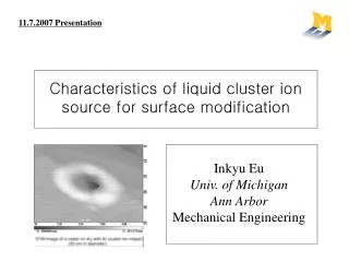
SEM Micrographs Elt. Conc. Co 52.046 wt.% Ni 28.060 wt.% Cr 0.505 wt.% Fe 1.032 wt.% P 11.764 wt.% Elt. Conc. Cr 18.193 wt.% Ni 10.377 wt.% Fe 70.722 wt.% Co-Ni SS304 Fresh SS304 12 mm 9.5 mm Elt. Conc. Co 64.075 wt.% Ni 29.646 wt.% Cr 0.518 wt.% Fe 4.785 wt% P 0.976 wt% Elt. Conc. Cr 6.082 wt.% Ni 8.704 wt.% Fe 84.901 wt.% SS304 500 h Co-Ni 500 h 12 mm 12 mm
XRD Result (Posttest) LiNiO2 and LiCoO2 LiFe5O8 LiFeO2
Separator Results SS304 EDAX 6.5 wt.% Cr Co-Ni-SS304 EDAX 0.24 wt.% Cr
Cyclic Voltammetric Results (650 ºC) CV done after 2hrs in CO3 melt with Cathode gas Scan rate: 10mV/s Potential: -1.6V to 0V
Tafel Polarization Results SS304 Co-Ni-SS304 ±250 mV OCP Scan rate: 25mV/s
Impedance Analysis (650 ºC) Frequency: 10 kHz-10 mHz ±5 mV OCP
Impedance Analysis (700 ºC) Frequency: 10 kHz-10 mHz ±5 mV OCP
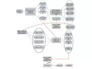
C1 C2 DPE1 DPE2 RW R1 R2 Electrical Equivalent Circuit Representation RW – Solution resistance R1 – Porous electrode ohmic resistance C1 – Coating capacitance R2 – Polarization resistance C2 – Double layer capacitance DPE1, DPE2 – Distributed Elements, Zarc-Cole type
Conclusions • Immersion test indicate a decrease in the chromium dissolution in the case of Co-Ni-SS304 • Surface composition of Co-Ni-SS304 consist mainly of Co and Ni oxides • Conductivity of the corrosion scale was higher in the case of Co-Ni-SS304 • Polarization resistance for oxygen reduction was significantly lower in the case of Co-Ni-SS304
Acknowledgements • Financial sponsors - Dept of Energy, National Energy Technology Laboratory