Download
1 / 27
270 likes | 395 Views
THERMAL AND STRESS ANALYSIS OF A SOLID DT TEST SPECIMEN. James K. Hoffer and J. Gregory Swadener. presented at the Laser IFE Workshop sponsored by The Department of Energy Offices of Fusion Energy Sciences & Defense Programs November 13, 2001.

E N D
THERMAL AND STRESS ANALYSIS OF A SOLID DT TEST SPECIMEN James K. Hoffer and J. Gregory Swadener presented at the Laser IFE Workshop sponsored by The Department of Energy Offices of Fusion Energy Sciences & Defense Programs November 13, 2001
Target Injection-1: Target Materials Response - LANL Overall Objective…………. Response of target materials to injection stresses FY 02 Deliverables……….. 1. Modify existing apparatus to accommodate new ‘DT strain cell.’ 2. Assemble and bench-test strain cell using no hydrogen (warm experiments, using ‘butter’). 3. Start experiments to measure DT yield strength and modulus. PI Experience………………. Extensive experience with DT and DT-layering (POC: J. Hoffer) Proposed FY02 Amount….. $ 200 k Relevance of Deliverables [X] NIF…………………… Research in materials in NIF targets [ ] Laser RR Facility…. [ ] Other DP/NNSA…… [X] Energy……………… Needed for injection into chamber Related DP activities…… Define experiments to measure the effect of a sudden thermal load on a DT-layered target
Finally, we enclose all of this assembly inside a tritium cell with optical ports:
Camera resolution field: 2mm x 2mm 1024 x 1024 pixels, 12 bit dynamic range, DT edges determined to < 1 m. What the camera might see:(version ‘A’)
Camera resolution field: 2mm x 2mm 1024 x 1024 pixels, 12 bit dynamic range, DT edges determined to < 1 m. What the camera might see:(version ‘B’)
Camera resolution field: 2mm x 2mm 1024 x 1024 pixels, 12 bit dynamic range, DT edges determined to < 1 m. What the camera might see:(version ‘C’)
What’s next? • Complete design of the “DT-strain cell” • Perform thermal modeling of layer formation • Perform strain analysis on proposed sample shape • Redesign cryostat if necessary • this assembly may be too long for existing apparatus
In fact, the “DT-strain cell” is not too large, but the optics don’t fit our existing cryostat: • existing “cold can” in optical cryostat • “DT-strain cell” • Existing “cold plate” • Closed cycle helium refrigerator second stage (10–20 K) plate
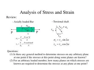
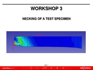
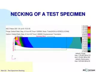
THERMAL & STRESS ANALYSES TYPICAL SPECIMEN SHAPE THERMAL EQUILIBRIUM SHAPE?
Hydrogenic solid shear strength datafrom ORNL H, D, T pellet experiments
MATERIAL PROPERTIES AT 18 K * estimate
THERMAL ANALYSIS – FE MESH 200 mm 1.0 mm
D2 Stress-Strain Response Bol’shutkin et al., 1970
THERMAL & STRESS ANALYSES TYPICAL SPECIMEN SHAPE THERMAL EQUILIBRIUM SHAPE?