Download
1 / 46
460 likes | 604 Views
The Future of Energy & Reduction in Greenhous e Emissions. Applied Filter Technology April 22 nd , 2010. APPLIED FILTER TECHNOLOGY, INC.

E N D
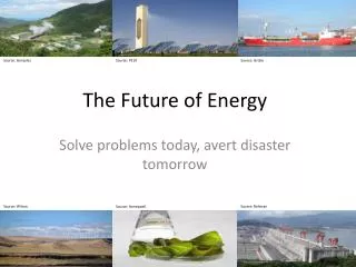
The Future of Energy & Reduction in Greenhouse Emissions Applied Filter Technology April 22nd, 2010
APPLIED FILTER TECHNOLOGY, INC. • Applied Filter Technology (AFT) facilitates the conversion of waste stream BioGas into energy. The energy output can be broken into two markets: the production of electricity and the production of Natural Gas. • BioGas is a mixture of methane and other gases produced from the decomposition of organic materials. It is produced naturally in landfills and from the processing of animal waste, sewage, crop waste, and cellulose and non-cellulose crops. April 22, 2010 2 Technical Presentation
BIO GAS PERSPECTIVE • A 1998 study by the United States Department of Energy concluded that in the US it is feasible to capture and use over a third of the biogas potential from landfills, animal waste and sewage or about 1.25 quadrillion BTU. If all this were used in transportation, it would displace 10 billion gasoline-gallon-equivalent per year. In the vehicle example this would reduce greenhouse gases by 500 million metric tons of CO2 per year or removing the emissions equivalent of 90 million light-duty gasoline vehicles from the road • storage. April 22, 2010 Technical Presentation
Applied Filter Technology • Opportunity and Challenge of BioGas for Sustainability • and Green House Emissions
Renewable Energy Cost Trends Levelized cents/kWh in constant $20001 4030 20 10 0 100 80 60 40 20 0 PV Wind COE cents/kWh 1980 1990 2000 2010 2020 1980 1990 2000 2010 2020 70 60 50 40 30 20 100 1512 9 6 30 10 8 6 4 20 Solar thermal Biomass Geothermal COE cents/kWh 1980 1990 2000 2010 2020 1980 1990 2000 2010 2020 1980 1990 2000 2010 2020 Source: NREL Energy Analysis Office (www.nrel.gov/analysis/docs/cost_curves_2002.ppt) 1These graphs are reflections of historical cost trends NOT precise annual historical data. Updated: October 2002
Total BIOGAS Quality Management • BIOGAS USE PRESENTS BOTH OPPORTUNITIES AND CHALLENGES • The future will include the effective use of Biogas for plant operations, grid power, and energy security. Engines and turbines will continue to play a larger role in this market. April 22, 2010 Technical Presentation
Experience • Applied Filter Technology • Experience that matters: • 167 operating systems on Biogas • First system on exhaust catalyst 1997 April 22, 2010 7 Technical Presentation
SUPPLY AND DEMAND ENERGY SECURITY DISTRIBUTED ENERGY TREND CONSUMER APPEAL (“GREEN”) RELEASE OF “GREENHOUSE” GASES REGULATORY – EMISSIONS (SOx, NOx, CO - California, New Jersey) ENERGY CREDITS – CO2, Greenhouse MARKET DRIVERS
THE AMERICAS Changing attitudes and market drivers are creating a bright future for technology companies in biogas processing and power generation. THE PACIFIC RIM China is driving the demand for traditional fuels forcing other Countries in the region to seek higher cost sources, and utilize biogas for power generation THE OPPORTUNITY
Market Overview • The historical use of biogas as a secondary heat source for digesters is rapidly being replaced as a valuable resource for reducing operating costs. • Drivers for change Include: • High cost of purchased energy • Aging equipment • Staff reductions • Plant upgrades • Equipment sensitivity • Environmental concerns • Green energy and carbon credits • Social conscience April 22, 2010 10 Technical Presentation
SAGPack Systems System Capacities from small microturbines to natural gas quality
Total BIOGAS Quality Management • Engineering Considerations • Effective baseline data • Design simulation and modeling • Gas utilization equipment matching • Total Plant integration • Long Term O/M plan • Supplier Qualifications April 22, 2010 Technical Presentation
Total BIOGAS Quality Management • Each BIOGAS has its own “Signature” • Methane Gas Content • Non-Methane Gas Fraction • Moisture Content • Sulfur Species Content • Volatile Organic Contaminants April 22, 2010 Technical Presentation
Total BIOGAS Quality Management Other Other Water Water Methane Methane CO2 CO2 BIOGAS “A” BIOGAS “B” April 22, 2010 Technical Presentation
Total BIOGAS Quality Management Siloxanes HVOCs Siloxanes HVOCs C6 to C12 H2S H2S Oxy. VOCs Oxy. VOCs C6 to C12 BIOGAS “A” BIOGAS “B” April 22, 2010 Technical Presentation
Total BIOGAS Quality Management • What are siloxanes? • Siloxanes are organosilicons added to many personal care products and are present in almost all biogas. • Typical levels are: • Landfills – 0.5 to 50 ppm v/v • Digesters – 0.5 to 140 ppm v/v April 22, 2010 Technical Presentation
Total BIOGAS Quality Management • Type of Siloxanes • Polydimethylsiloxanes - [Me2SiO]x - • (MM, MDM, MD2M) are highly volatile. • Cyclomethicones [Me2SiO]x • D3, D4, D5, D6 are not highly volatile • None are regulated as VOC or ODC. April 22, 2010 Technical Presentation
Total BIOGAS Quality Management • Polydimethylsiloxane Chemical Formula CH3CH3 H3CSi O Si CH3 CH3CH3 MM April 22, 2010 Technical Presentation
Total BIOGAS Quality Management • Cyclomethicone Chemical Formulas CH3 CH3 CH3 CH3 Si Si O O O O H3C H3C CH3 CH3 Si Si H3C H3C CH3 CH3 Si Si O O O Si CH3 CH3 D3 D4 April 22, 2010 Technical Presentation
Concentration Range, ppbv ppbv Organic Silicon Species Low High Average No. of Hits Butoxytrimethylsiloxane 1 --- --- 920 Methoxytrimethylsilane 1 --- --- 227 1,1,3,3-Tetramethyldisiloxane 1 --- --- 85 Pentamethyldisiloxane 2 51 100 76 Hexamethyldisiloxane (MM) 10 46 2,260 847 Octamethyltrisiloxane (MDM) 12 32 465 183 Hexamethylcyclotrisiloxane (D3) 5 285 8,700 2,155 Octamethylcyclotetrasiloxane (D4) 46 33 20,144 2,456 Decamethylcyclopentasiloxane (D5) 47 102 18,129 3,422 Dodecamethylcyclohexasiloxane (D6) 3 37 765 352 Tetramethylsilane 1 --- --- 170 Trimethylfluorosilane 1 --- --- 610 Trimethylpropoxysilane 1 --- --- 5,200 Total BIOGAS Quality Management April 22, 2010 Technical Presentation
Total BIOGAS Quality Management • Combustion of Siloxane D5 • C10Si5H30O5 (D5) + 15O2 5SiO2 + 10CO + 15H2O • Mass: 370.8 479.7 300.4 280 270.1 • Or C10Si5H30O5 (D5) + 20O2 5SiO2 + 10CO2 + 15H2O • Mass: 370.8 639.6 300.4 440 270.1 • A 140 CFM gas stream containing 0.5 ppm v/v D5, upon combustion will generate almost 60 pounds per year of silicon dioxide, the main constituent of sand. April 22, 2010 Technical Presentation
Total BIOGAS Quality Management • Deposits are formed containing mostly silica and silicates (SiO2 and SiO3), but can also contain calcium, copper, sodium, sulfur, and zinc. April 22, 2010 Technical Presentation
Total BIOGAS Quality Management April 22, 2010 Technical Presentation
Total BIOGAS Quality Management Steps in Complete SAGPackTM Treatment Process • Removal of hydrogen sulfide • Gas chilling • Removal of water vapor • Removal of siloxanes • Gas Compression • Gas Drying • Removal of halogenated organic species (low molecular weight contaminants containing bromine, chlorine, and fluorine); • Separation of the methane from the carbon dioxide (methane content upgrade). April 22, 2010 Technical Presentation
Total BIOGAS Quality Management CISTM Process in SAGPackTM Treatment System April 22, 2010 Technical Presentation
Total BIOGAS Quality Management Moisture Removal in SAGPackTM Treatment Process April 22, 2010 Technical Presentation
Total BIOGAS Quality Management SAGPackTM System with H2S and Siloxane Removal April 22, 2010 Technical Presentation
Total BIOGAS Quality Management Dublin San Ramon WWTP, CA April 22, 2010 Technical Presentation
Total BIOGAS Quality Management Riverside WWTP, CA April 22, 2010 Technical Presentation
Oro Loma SAGPack™ System Digester Gas-300 scfm
Total BIOGAS Quality Management City Brew, La Crosse WI March 30, 2010 Technical Presentation
Total BIOGAS Quality Management Glacier Ridge, WI April 22, 2010 Technical Presentation
Total BIOGAS Quality Management Madison, WI April 22, 2010 Technical Presentation
Total BIOGAS Quality Management Tulare, CA SAGPackTM System April 22, 2010 Technical Presentation
40 0F at Pressure Dew Point Gas Source Coalescer Condenser Compressor 90-100 0F Gas/Gas Exchanger 200 0F Gas/Liquid Exchanger Chiller Booster( 5 psig ) Drain Drain 77 0F 130 psig Drain Drain HeatExchanger 112 0F 300 0F Hot Gas Source 80 0F Condenser Regenerant Gas To Discharge V5 V4 V3 V1 V2 Drain 125 psig Heat to Recovery H2S Removal 98% + Methane To Pipeline 600 psig + Stage 1 Stage 2 Compressor PSA System 98% + Industrial Grade CO2 Vehicle Fuels and Upgrade April 22, 2010 Technical Presentation
Refined Biogas Clean Media Dirty Media VOC-Rich Regenerant Gas To Flare or Thermal Oxidizer VOC Removal Vessel Regeneration Vessel Clean, Hot Regenerant Gas Crude Biogas From Inert Gas Generator 300 to 600 oF Cooling Stage Pneumatic Conveyance AFT SWOPTM (Thermal Swing Operated Biogas Purification Process) Regenerable Technology Options April 22, 2010 Technical Presentation
Microwave Regeneration and Oxidation Media with contaminants Biogas with water, hydrocarbons, siloxane and H2S Vent Hydrocarbon oxidation reactor H2S oxidation reactor Media adsorber Microwave Reactor Sulfur capture Carbon filter SiO2 capture Cleaned Biogas Water and liquid hydrocarbons (with siloxane) Nitrogen Regenerated media
Capabilities • Project feasibility and gas testing • System design and supply • Removal of • Sulfur, moisture, VOC, siloxanes • Gas Upgrading • System Operations • Long Term Service Support April 22, 2010 45 Technical Presentation
Total BIOGAS Quality Management • Summary • The AFT Difference • Packaged Systems matched to end use products • Long Term System Support with trained service people • Sales and support thru the established network of dealers • Parts and Service provided and supported by AFT • Plug and Play treatment processes on each site specific gas • Proper sizing and design of treatment processes • Ongoing BIOGAS influent and effluent testing to assure consistent engine performance April 22, 2010 Technical Presentation