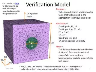
Model-based Design Verification IVV Annual Workshop
260 likes | 285 Views
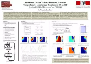
This workshop focuses on model-based design verification, discussing topics such as design verification planning, iterative verification process, perspectives on verification, as-built design, and more.

Model-based Design Verification IVV Annual Workshop
E N D
Presentation Transcript
Model-based Design VerificationIVV Annual Workshop September, 2009 Tom Hempler
Agenda • Design & Integration Verification Planning • Iterative Verification Process • Perspectives on Verification As-Built Design • Verification Goals and Objectives • Design Verification Process • Design Verification Methods
Software Design & Integration Verification Work Plan • Using criticality and risk analysis results from PBRA, plan IV&V verification tasks • Review risk assessment results from PBRA • Review software, interface, and integration design risks identified by the PBRA • Review and target developer artifacts related to mission critical and safety critical behavior • Identify critical software design and integration topologies and protocols • Review schedule risks associated with development schedule and milestones • Integrate design verification schedule with engineering services master schedule
Iterative Verification Process • Design verification is accomplished iteratively at multiple levels during all lifecycle phases • Evaluate how well software components interact and support validated capabilities, limitations, and performance requirements. • The System Reference Model (SRM) contains the structure and behavior used as a baseline for verification • Mission and safety critical software components and their interactions are compared with as-designed software components • SRM component operations, attributes, and services are functionality and performance requirements of the system • Non-functional requirements such as reliability, safety, scalability, recoverability, security, and availability • Perspectives on the design along with scenarios facilitate verification and reveal program/technology risks
System Under Development System Reference Model Functional Capabilities & Limitations Structure Relationships Behavior Constraints Services Physical Software and Interface Design Verification Views Design Verification- Relationships -
Relationships Perspective • Relationships defined as having size, weight, physical features, and performance properties • Relationships among capabilities and limitations are dependencies, associations, and design or performance constraints. • Relationships among physical components are interactions, services provided/consumed, containership, ownership, controller-terminal roles, etc. • Verification is accomplished among all critical relationships described in SRM structure and behavior • Diagrams: • Structure Diagrams • Behavior Diagrams
System Under Development System Reference Model Functional Capabilities & Limitations Structure Relationships Behavior Constraints Services Physical Software and Interface Design Verification Views Design Verification- Physical -
Physical Perspective • Features: • Describes the physical features and interrelationships among software components • Useful for identifying software and hardware; and software component interdependencies • Describes deployment configurations in terms of multiple instantiations, redundancy, and their interaction • Describes systems, sub-systems and components using classes; and their capabilities and limitations using attributes • Logical design provides facility to describe software domain; and their capabilities and limitations using attributes • Diagrams: • Structure Diagrams with design and performance constraints • Behavior Diagrams
System Under Development System Reference Model Functional Capabilities & Limitations Structure Relationships Behavior Services Physical Software and Interface Design Verification Views Design Verification- Capabilities & Limitations-
Capabilities & Limitations Perspective • Features: • SRM structure provides facility to describe software domain; and their capabilities and limitations using attributes • Accounts for non-functional properties such as availability, reliability (fault tolerance), availability, safety, performance (throughput), and scalability • Addresses resource sharing, concurrence • Useful for identifying design where processes can be controlled (initialization, recovery, reconfiguration, shut down) • Provides facility to verify performance, safety, dependability and other non-functional characteristics of systems, sub-systems and components • Diagrams: • Structure Diagrams with design and performance constraints
System Under Development System Reference Model Functional Capabilities & Limitations Structure Relationships Behavior Services Physical Software and Interface Design Verification Views Design Verification- Functional-
Functional Perspective • Features: • Systems and sub-system components (e.g., program libraries, or architecture layers) are allocated operations that define the functionality of the design • Provides a look into the environment that surrounds the system and the effects (adverse or otherwise) it has on it • Serves as a basis for viewing validated requirement allocation and human interface allocations to the system • Useful for identifying work done by teams/individuals, cost evaluation and planning, progress monitoring, reasoning about software reuse, portability and security • Domain model contains operations or activities that describe systems, sub-systems and components using classes, and their capabilities using attributes and operations • Diagrams: • Structure diagrams • Behavior diagrams
System Under Development System Reference Model Functional Capabilities & Limitations Structure Relationships Behavior Services Physical Software and Interface Design Verification Views Design Verification- Services-
Services Perspective • Features: • Uses a set of use cases, activities or sequences of interactions between objects and between processes that weaves a behavioral thread through the design • Useful for realizing architectural elements used during software and interface design • Also used for verification of interface design to identify preventative measures taken for adverse behaviors • Diagrams: • Structure Diagrams • Behavior Diagrams
Design Verification Goal/Objectives • Goal • Ensure that the proposed software and integration design adequately satisfies the software architecture and validated requirements and behavior. An adequate design is determined by assessing it for completeness, correctness, consistency, ambiguity, and testability. • Objectives • Ensure the integration design is a correct, accurate and complete transformation of the validated behavior • Ensure that no unintended features were introduced during the design phase and that the design guards against undesirable behavior • Ensure that the Integration design is consistent with the verified software architecture and validated behavior • Ensure that the proposed design is testable • Verify interfaces define services to be provided and/or consumed, the preconditions for invoking the interface, the post conditions, and the invariants. • Ensure design documentation is acceptable and will support follow-on verification and future maintenance activities • Verify that the interface design isolates behavioral components from each other, and from computational components and data stores.
Answering Three Questions • Using validated requirements and behavior • Verify that the system software design provides for the specified capabilities, limitations, and behavior. • Verify that the system software design guards against undesirable behavior • Verify that the system software design provides self protection and recovery capability against adverse conditions
Definitions for Software Design and Integration Quality Factors Design verification check list • Unambiguous – The documentation is legible, understandable, and could result in only one interpretation by the intended audience. – All acronyms, mnemonics, abbreviations, terms, symbols, and special design languages are defined. • Correct – The software design satisfies the software architecture and validated requirements (i.e., behaviors in the SRM, as well as non-functional requirements like safety or other “…ility”-like requirements). – The software design complies with applicable Mission and NASA standards, references, and policies. • Complete – There is a logical decomposition into subsystems and modules, and their interactions are specified. – The hardware, software, and user interfaces are specified to an appropriate level. An appropriate level is one that identifies the information being processed, communication mechanisms and protocols, and services that particular subsystems or modules provide (i.e., behaviors that are changed or affected based on communication between two modules). – Functionality (e.g., algorithms, state/mode definitions, input/output validation, exception handling, reporting, and logging) is specified at the appropriate level of decomposition. – Performance criteria (e.g., timing, sizing, speed, capacity, accuracy, precision, safety, and security) are specified at the appropriate level of decomposition. • Consistent – States and state transitions are used similarly throughout the design. For example, if event ε triggers Object1 to transition to state A, then elsewhere in the design that same event shall not cause Object1 to transition to a state other than A. – All terms and concepts are used similarly within the design itself, as well as with external artifacts such as the system and software architectures. • Testability – There are objective acceptance criteria such that the design can be shown to pass or fail.
Design Verification Process • Constraints • Task Preconditions • Software architecture verification has been started • SRM products necessary to support design verification have been completed and validated • A criticality assessment has been made • PBRA determined the prioritization and scope of the verification effort, including the level of analysis applied to each component/behavior • Artifacts necessary to support software design verification provided by Project • Task Inputs • Software design material • Validated software requirements • Verified software architecture • SRM elaborated to a level indicative of software detailed design • Task Outputs/Deliverables • IV&V evaluation of project’s responses to identified deficiencies/issues are documented & tracked • task status, schedules & risks documented & reported on regular basis • Report that documents IV&V assessment of software design • Model Correlation Matrix has been updated based on verified software design • Findings/recommendations for SRM changes/additions
Design Verification Methods • Inspection • Analysis • Demonstration • Test
Design Verification - Inspection • Inspection • Review and compare artifacts with validated behavior • Verify that the design can be implemented • Verify that the design is traceable to the validated requirements and behavior • Verify that software design and integration design is complete and correct • Verify that omissions, defects, and ambiguities in the design are detected and recorded.
Design Verification - Analysis • Analysis • Verify through software structure analysis that the design integrity goals are met and interrelationships described in the behavior model exist • Verify that fault recovery strategies described in the validated behavior model are employed. • Verify that the design is traceable to the validated requirements and behavior • Verify that software design and integration design is complete and correct • Verify that omissions, defects, and ambiguities in the design are detected and recorded.
Design Verification - Demonstration • Demonstration Evaluation • Verify that software and integration design is testable within the behavior model • Verify relationships between the validated behavior and the software component features and integration properties • Apply assertions used on the logical model to components of the physical model • Verify that the design is traceable to the validated requirements and behavior • Verify that the design supports critical capabilities • Verify that integration logic is complete and correct • Verify that omissions, defects, and ambiguities in the design are detected and recorded.
Design Verification - Test • Test and Evaluation • Verify that software and integration design is testable within the behavior model • Verify relationships between the validated behavior and the software component features and integration properties • Apply assertions used on the logical model to components of the physical model • Verify that the design is traceable to the validated requirements and behavior • Verify that the design supports critical capabilities • Verify that integration logic is complete and correct • Verify that omissions, defects, and ambiguities in the design are detected and recorded.
Summary • Design & integration verification planning is a critical first step in an executable process • Iterative verification processes are necessary to accomplish verification at all levels of design • Perspectives on verification are necessary to maintain context and accomplish goals • Verification goals and objectives are defined • Design verification process is implemented • Design verification methods are model-based, independent , and objective