Download
1 / 35
350 likes | 404 Views
Vibrating fork sensor Supplier vibranivou00ae vn 1030 with tube extension for point level measurement Supplier, Exporter in India<br>For More Information visit on:- www.seeautomation.com<br>Our Mail I.D:- sales@seeautomation.com<br>Contact Us:- 91-11-22012324 , 8144883403<br>

E N D
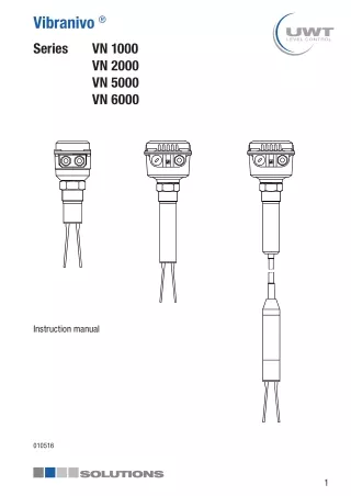
Vibranivo ® Series VN 1000 VN 2000 VN 5000 VN 6000 Instruction manual 010516 1
UWT GmbH Westendstraße 5 D-87488 Betzigau Tel.: +49 (0)831 57123-0 Internet:www.uwt.de Fax: +49 (0)831 76879 E-Mail: info@uwt.de Scope of this instruction manual: Types VN 1020 1030 1050 VN 2020 2030 2050 VN 5020 5030 5050 VN 6020 6030 6050 CE / TR-CU Approval ATEX 1D 1/2D IEC-Ex t IIIC Relay (SPDT, DPDT) 2-wire without contact Electronic modules PNP 2
Table of Contents Safety /warning notes Page 4 Fields of application Page 4 Technical Data Page 5 Application Page 14 Installation Page 17 Spare parts Page 21 Electrical connection Page 24 Switching logic Page 28 Maintenance Page 30 Assembly VN *020 separate housing Page 31 ATEX / IEC-Ex Notes Page 32 3
Safety /warning notes Installation, maintenance and commissioning may be accomplished only by qualified technical personnel. For terminal connection of the device, the local regulations or VDE 0100 (Regulations of German electrotechnical Engineers) must be observed. All field wirings must have insulation suitable for at least 250V AC. The temperature rating must be at least 90°C (194°F). In the case of handling by untrained personnel or handling malpractice, the safety of the device cannot be guaranteed. Fields of application Level limit switch for level limit detection in powder and bulk materials. 4
Technical Data °C VN 1020 VN 2020 130mm (5.1“) 290mm (11,4“) R 1 1/2“ NPT 1 1/2“ 1.4301 (304) 1.4541 (321) 1.4404 (316L) A B 1.4404 1.4581 (316L) A B A, B 11 °C 1 12 2 12 -1 .. +16bar (-14.5 .. +232psi) -1 .. +16bar (-14.5 .. +232psi) ~ 1,6kg (3.5 lbs) ~ 2,3kg (5 lbs) 5
°C VN 1030 VN 2030 130mm (5.1“) 290mm (11,4“) R 1 1/2“ NPT 1 1/2“ 1.4301 (304) 1.4541 (321) 1.4404 (316L) L B L 1.4404 1.4581 (316L) B B, L 11 °C 1 / 2 12 2 12 -1 .. +16bar (-14.5 .. +232psi) -1 .. +16bar (-14.5 .. +232psi) ~ 1,6kg (3.5 lbs) +2,5kg/m (+5.5 lbs per 39.9“) (L) ~ 2,3kg (5 lbs) +2,5kg/m (+5.5 lbs per 39.9“) (L) 6
°C VN 1050 VN 2050 130mm (5.1“) R 1 1/2“ NPT 1 1/2“ 1.4301 (304) 1.4541 (321) 1.4404 (316L) L B 1.4404 1.4581 (316L) B, L 11 °C 3 12 -1 .. +6bar (-14.5 .. +87psi) ~ 4,0 kg (8.8 lbs) + 0,5 kg/m (+1.1 lbs per 39.9“) (L) 7
°C VN 5020 VN 6020 125mm (4.92“) 285mm (11.2“) R 1 1/2“ NPT 1 1/2“ 1.4301 (304) 1.4541 (321) 1.4404 (316L) A B 1.4404 1.4581 (316L) A B A, B 11 °C 1 12 2 12 -1 .. +16bar (-14.5 .. +232psi) -1 .. +16bar (-14.5 .. +232psi) ~ 2,1kg (4.6 lbs) ~ 2,8kg (6.2 lbs) 8
°C VN 5030 VN 6030 125mm (4.92“) 285mm (11.2“) R 1 1/2“ NPT 1 1/2“ 1.4301 (304) 1.4541 (321) 1.4404 (316L) L B 1.4404 1.4581 (316L) L B B, L 11 °C 1 / 2 12 2 12 -1 .. +16bar (-14.5 .. +232psi) -1 .. +16bar (-14.5 .. +232psi) ~2,1kg (4.6lbs) +2,5kg/m (+5.5 lbs per 39.9“) (L) ~2,8kg (6.2lbs) +2,5kg/m (+5.5 lbs per 39.9“) (L) 9
°C VN 5050 VN 6050 125mm (4.92“) R 1 1/2“ NPT 1 1/2“ 1.4301 (304) 1.4541 (321) 1.4404 (316L) L B 1.4404 1.4581 (316L) B, L 11 °C 3 12 -1 .. +6bar (-14.5 .. +87psi) ~ 4,5 kg (9.9 lbs) + 0,5 kg/m (+1.1 lbs per 39.9“) (L) 10
A B L VN 1020 VN 1030 VN 1050 165mm (6.5”) 100mm (3.94”) 100mm (3.94”) 100mm (3.94”) max. 4.000mm (157.5”) max. 7.000mm (276”) VN 2020 235mm (9.25”) (1) 260mm (10.2”) 170mm (6.69”) (1) 195mm (7.68”) 170mm (6.69”) (1) 195mm (7.68”) 170mm (6.69”) (1) 195mm (7.68”) VN 2030 max. 4.000mm (157.5”) VN 2050 max. 20.000mm (787”) VN 5020 VN 5030 VN 5050 165mm (6.5”) 100mm (3.94”) 100mm (3.94”) 100mm (3.94”) max. 4.000mm (157.5”) max. 7.000mm (276”) VN 6020 235mm (9.25”) (1) 260mm (10.2”) 170mm (6,69”) (1) 195mm (7.68”) 170mm (6.69”) (1) 195mm (7.68”) 170mm (6.69”) (1) 195mm (7.68”) VN 6030 max. 4.000mm (157.5”) VN 6050 max. 20.000mm (787”) (1) Option switching sensitivity > 5 g/ l (0.3 lb/ft³) 11
°C 1 Tamb 60°C (140°F) Tamb 40°C (104°F) Tprocess Tprocess -40°C (-40°F) 100°C (212°F) 150°C (302°F) -40°C (-40°F) 2 Tamb 60°C (140°F) ø 50mm (ø 1.97“) 180 mm (7.1“) Tamb Tprocess 150°C (302°F) Tprocess -40°C (-40°F) -40°C (-40°F) 3 Tamb Tamb 60°C (140°F) Tprocess Tprocess -25°C (-13°F) 80°C (176°F) -25°C (-13°F) 12
Sensitivity B g/l 50 20 / 5 (1) 50 20 / 5 (1) 1g/l = 0.06 lb/ft³ A g/l 150 75 150 75 VN 1000 VN 2000 VN 5000 VN 6000 (1) Option switching sensitivity > 5 g/ l (0.3 lb/ft³) Bulk material d < 10mm (0.39“) 13
Application VN 1020 VN 2020 VN 5020 VN 6020 (2) (1) 200mm (7.87“) max.600N (1) (2) Mech. load of the sensor Protective angle (canopy) in case of high mechanical load 14
VN 1030 VN 2030 VN 5030 VN 6030 (2) < 300Nm (1) max. L / mm ( ” ) 4.000 (157.5 ) 1.200 (47.2 ) 600 (23.6 ) α L < 5° < 45° > 45° < 300Nm (1) α (1) (2) Mech. load of the sensor Sliding sleeve: Tighten straining screws with 20Nm 15
VN 1050 VN 2050 VN 5050 VN 6050 max.2kN (1) (1) Mech. load of the sensor 16
Assembly Fixing Threads Teflon tape or flat gasket 80Nm Fixing Flanges Gasket 17
Fixing EHEDG 100Nm (4) (3) (2) (1) (1) Certified flush welding socket must be used (2) Metal-metal support without any gap (3) Sealing ring (4) Welding (observe hygiene requirements) 18
Alignment (1) (1) (1) Ingress protection IP 66 / IP67 19
Treatment Option: Weather protection cover for Ex only approved for Zone 22 20
Spare parts CE / ATEX / IEC-Ex: VN 1020 VN 1030 CE / ATEX / IEC-Ex: VN 5020 VN 5030 100mm (3.94“) ATEX / IEC-Ex: VN 1050 ATEX / IEC-Ex: VN 5050 CE: VN 1050 CE: VN 5050 pl100932 pl100120 pl100932 pl100120 19...230V 50/60 Hz 19...55V DC pl100247 pl100052 pl100247 pl100052 19...230V 50/60 Hz 19...55V DC pl100246 pl100123 pl100246 pl100123 18...50V DC PNP pl100242 pl100122 pl100122 pl100172 19...230V AC/DC 21
CE / ATEX / IEC-Ex: VN 2020 VN 2030 CE / ATEX / IEC-Ex: VN 6020 VN 6030 170mm (6.69“) ATEX / IEC-Ex: VN 2050 ATEX / IEC-Ex: VN 6050 CE: VN 2050 CE: VN 6050 pl100930 pl100124 pl100930 pl100124 19...230V 50/60 Hz 19...55V DC pl100193 pl100050 pl100193 pl100050 19...230V 50/60 Hz 19...55V DC pl100176 pl100127 pl100176 pl100127 18...50V DC PNP pl100182 pl100126 pl100126 pl100126 19...230V AC/DC 22
CE / ATEX / IEC-Ex: VN 2020 VN 2030 CE / ATEX / IEC-Ex: VN 6020 VN 6030 195mm (7.68“) ATEX / IEC-Ex: VN 2050 ATEX / IEC-Ex: VN 6050 CE: VN 2050 CE: VN 6050 pl100931 pl100128 pl100931 pl100128 19...230V 50/60 Hz 19...55V DC pl100194 pl100051 pl100194 pl100051 19...230V 50/60 Hz 19...55V DC pl100173 pl100131 pl100173 pl100131 18...50V DC PNP pl100187 pl100130 pl100130 pl100130 19...230V AC/DC 23
Electrical connection All electronic modules: Over voltage category II Relay SPDT max. 4mm² (AWG12) 1 2 3 4 5 max. 10A, HBC, 250V, T/F AC max. 253V, 4A, 500VA DC max. 253V, 4A, 60W PE + - L N (1) 19...230V +10% (3) 50/60Hz 8VA 19... 50V +10% DC 1,5W (2) 2225Vrms (1) (2) (3) Power supply Isolating voltage including 10% from EN 61010 24
Relay DPDT max. 4mm² (AWG12) 1 2 3 4 5 7 8 9 (4) max. 10A, HBC, 250V, T/F (4) (4) PE + - L N AC max. 253V, 4A, 500VA DC max. 253V, 4A, 60W (1) 19...230V +10% (3) 50/60Hz 18VA 19... 50V +10% (3) DC 2W 2225Vrms (2) 2225Vrms (1) (2) (3) Power supply Isolating voltage including 10% from EN 61010 25
PNP max. 4mm² (AWG12) 1 2 3 max. 0,4A (2) (2) max. 4A HBC, 250V, T/F PE + - (1) 18... 50V +10% (3) DC 1,5W (1) (3) Power supply including 10% from EN 61010 26
2-wire without contact max. 4mm² (AWG12) 1 2 min. 10mA max. 500mA max. 2A < 200ms max. 5A < 50 ms (2) (1) 19...230V +10% (3) 50/60Hz 1,5VA / DC 1W PE + - L N (2) max. 4A HBC, 250V, T/F max. 7V max. 5mA 1 2 1 2 (1) (3) Power supply including 10% from EN 61010 27
Switching logic FSL FSH (1) 3 4 5 3 4 5 (2) 3 4 5 7 8 9 3 4 5 7 8 9 (3) 1 3 1 3 (4) 1 2 1 2 (5) (1) 3 4 5 3 4 5 (2) 3 4 5 7 8 9 3 4 5 7 8 9 (3) 1 3 1 3 (4) 1 2 1 2 (5) (1) = Relais SPDT (2) = Relay DPDT (3) = PNP (4) = 2- wire without contact (5) = LED Signal 28
Signal delay (Relay DPDT) (1) (2) T1 t T2 0-30 sec. 0 T1 30 0 T1 30 1 2 3 4 5 7 8 9 (2) (1) = level (2) = relay output 29
Maintenance Cleaning 30
Assembly Separate housing (selection: pricelist pos.26) VN 1020 VN 2020 VN 5020 VN 6020 white red shield black VN 1030 VN 2030 VN 5030 VN 6030 31
ATEX II 1D 1/2D + IEC-Ex t IIIC Da, Da/Db Notes Permitted relative pressure -0,2...+0,1bar (-2.9…+1.45psi) Zone borders VN 1020/1030 VN 2020/2030 VN 5020/5030 VN 6020/6030 VN 1020 VN 2020 VN 5020 VN 6020 VN 1030 VN 2030 VN 5030 VN 6030 VN 1050 VN 2050 VN 5050 VN 6050 1D 2D Da Db 20 21 (1) (2) (3) 1D 1D Da Da 20 20 (1) (2) (3) (1) Category (2) EPL (IEC-Ex) (3) Zone 32
Ambient temperature max. Surface temperature T 80°C (176°F) 90°C (194°F) 100°C (212°F) 110°C (230°F) 120°C (248°F) 130°C (266°F) 140°C (284°F) 150°C (302°F) 120°C (248°F) 120°C (248°F) 120°C (248°F) 120°C (248°F) 120°C (248°F) 130°C (266°F) 140°C (284°F) 150°C (302°F) 60°C (140°F) The data of the table are valid, if it is guaranteed due to the installation that the thread part has a maximum temperature of 80°C (176°F) at normal use. max.80°C (176°F) 33
Installation VN 1000 VN 2000 (1) (2) VN 5000 VN 6000 (1) (2) (1) (2) A pull relief must be provided Connect with equipotential bonding of the plant 34
ATEX / IEC-Ex: Further Remarks For installation and field wiring the respectively valid installation regulations of the respective country must be observed. Commissioning only with closed lid. Do not remove the lid (cover) while circuits are alive. Before opening the lid take care, that no dust deposits or whirlings are present. The installation has to be carried out in a way, that mechanical friction or impact does not cause sparks between the aluminium enclosure and steel. If installing the whole unit in zone 20, the power supply shall be rated for a prospective short circuit current of not more than 10kA (details of EN 60079-14 must be obeyed) Cable glands: Installation according to the regulations of the country, where the product is installed. Not used entries have to be closed with blanking elements certified for this purpose. Where applicable the factory provided parts must be used. A strain relief must be provided for the field wiring cables, when the device is installed with the factory provided cable glands. The diameter of the field wiring cable must match to the clamping range of the cable clamp. If other than the factory provided parts are used, following must be ensured: The parts must have an approval adequate to the approval of the level sensor (certificate and type of protection). The approved temperature range must be from the min. ambient temperature of the level sensor to the max. ambient temperature of the level sensor increased by 10 Kelvin. The parts must be mounted according to the instructions of the supplier. 35